Rehman Plaza, Sanda Khurd, Bund Road, Lahore, Pakistan

Irrigation & Canal Projects

Irrigation & Canal Projects — REW | Sluice Gates, Penstocks & Valves Since 1948
Home/ Industries/ Irrigation & Canal Projects
REW Industries · Irrigation & Canal Projects

Water Control for
Canal Infrastructure

Barrage & Headworks
Main Canal Regulators
Distributaries & Minors
Outlets & Watercourses
Lift & Drainage Stations
Tubewell Networks
Head · Reach · Tail

Pakistan runs the largest contiguous canal system in the world — over 60,000 km of canals fed from the Indus and its tributaries, serving roughly 16 million hectares of irrigated land. Every acre of that command depends on gates that lift under head, regulators that hold their setting, outlets that deliver an equitable share and pumps that keep drainage moving. REW manufactures sluice gates, penstocks, trash racks, sluice and air valves, pipes and pumps for that system — in Lahore, since 1948.
Rehman Engineering Works · Lahore, Pakistan Supplying irrigation departments since 1948 ISO 9001:2015 · PSQCA Marked
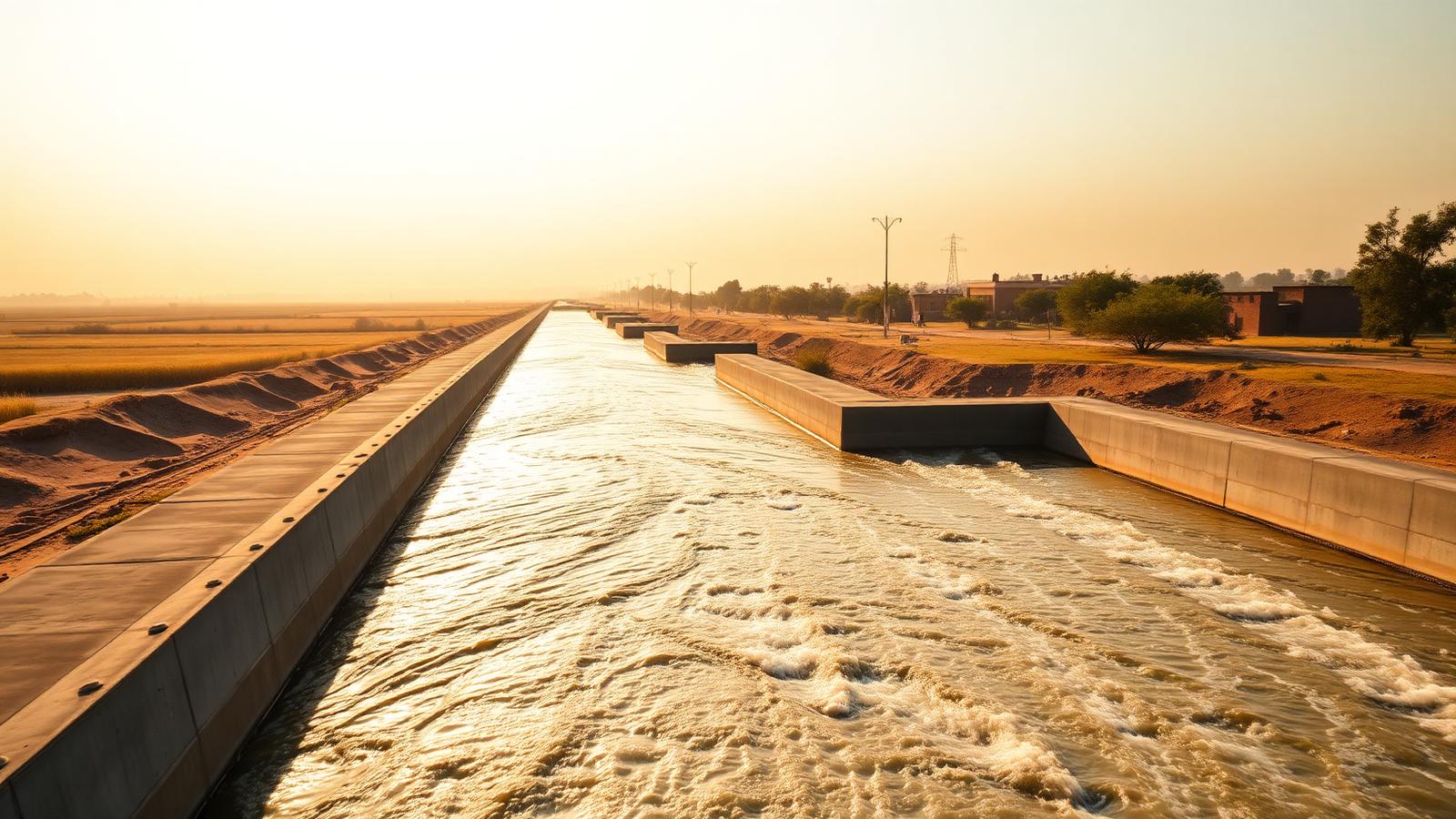
Canal head regulator with steel sluice gates and hand-operated hoisting stands REF · IRR-2026 Canal Head Regulator · Gate Bay
Scheme Ledger
Fabricated Steel Penstocks & Cast Iron Sluice Gates
Headstocks, Spindles & Gearbox Hoisting Arrangements
Trash Racks, Screens & Embedded Frames
Barrage to Watercourse Full Chain Coverage
Lahore, Pakistan · Since 1948
1948
Manufacturing Since
60,000 km
Canal Network Served by the System
100%
Gates Trial-Assembled & Tested
ISO 9001
Certified Quality System
Structures · Barrage · Regulator · Fall · Outlet Design References · IS 3042 · IS 5620 · BS · AWWA Seating Heads up to 10 m Manufacturing · Since 1948 Approved · Irrigation Departments & WASA Hot-Dip Galvanised & Epoxy Coated Options
Scroll
Industry Overview

Engineering for Head, Silt and Equity

The Indus Basin Irrigation System is a gravity system. Water diverted at a barrage travels hundreds of kilometres through main canals, branch canals, distributaries and minors before it reaches an outlet and a farmer's watercourse. There are no pumps in most of that chain to correct a mistake — level, slope and gate setting do all the work.

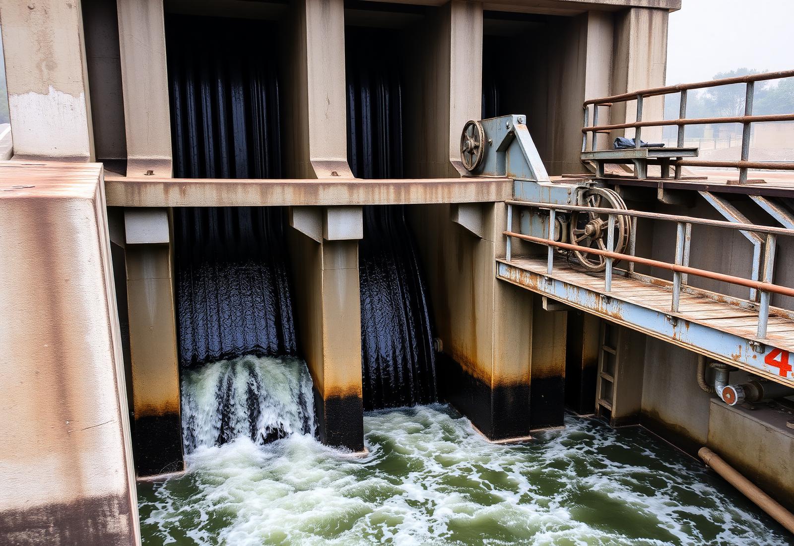
At the head, barrage and head-regulator gates operate under high seating head, against silt-laden water and seasonal flood loading. Gate leaves, embedded frames, seals and hoisting gear must lift reliably after months of standing still.

Along the reach, cross regulators and falls hold upstream water level so that every distributary offtake continues to draw its designed discharge. A regulator that cannot hold its setting shifts water from tail to head and creates the tail-end shortage that dominates farmer complaints.

At the tail, outlets, watercourse structures, sluice valves and tubewell delivery lines decide how much of the released discharge actually arrives at the field. Conveyance losses in unlined and poorly gated watercourses are widely estimated at 30–40% between the outlet and the crop.

Add to this the load case nobody designs away: abrasive silt, seasonal drawdown, brackish groundwater in drainage areas, and maintenance carried out by a canal beldar with a spanner during a short annual closure. Equipment for this industry must be simple, heavy, repairable in place, and available as spares for decades.
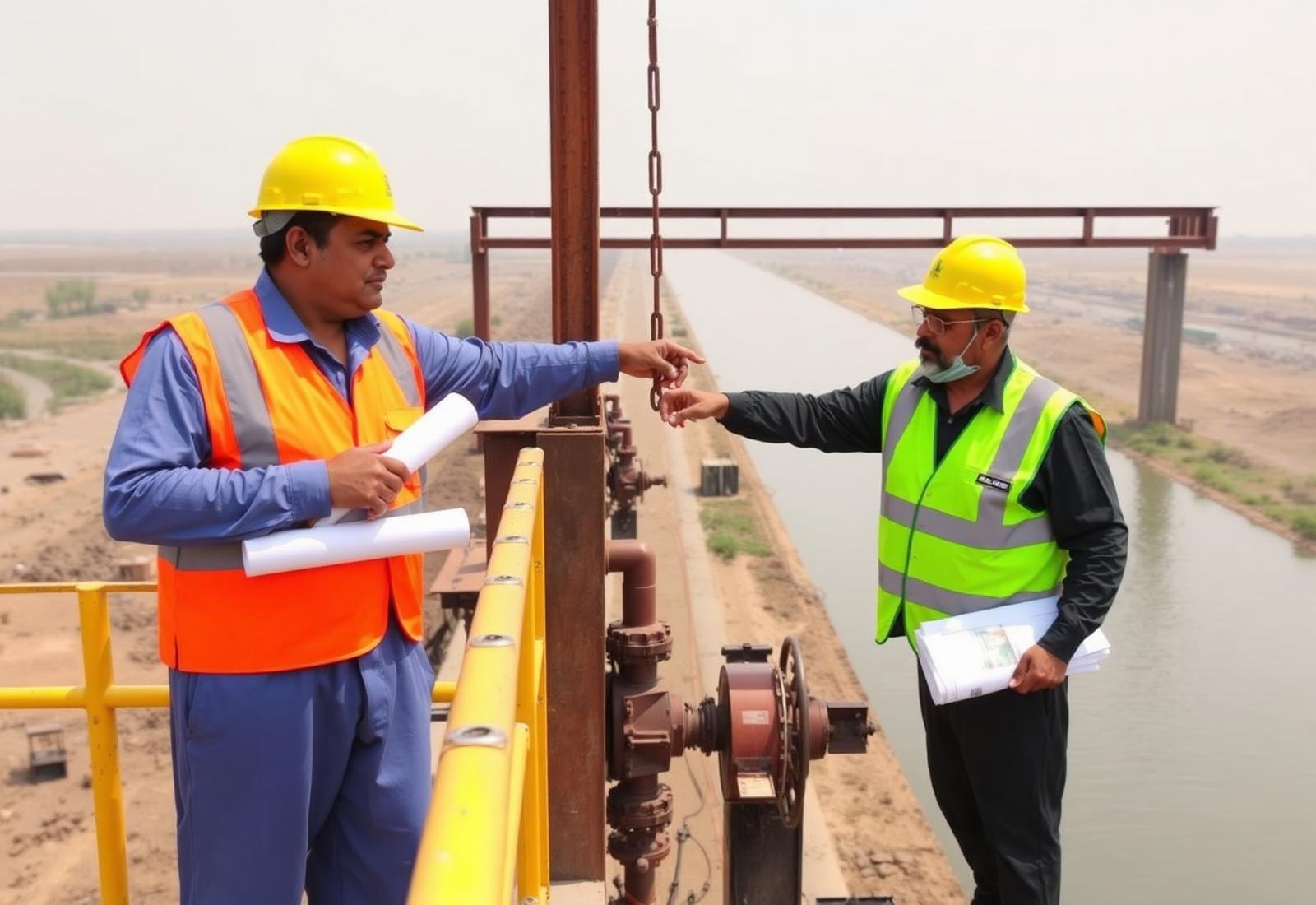
Irrigation engineers inspecting a canal regulator hoisting arrangement
Fig. 1 Gate schedule verified against the regulator structure drawing
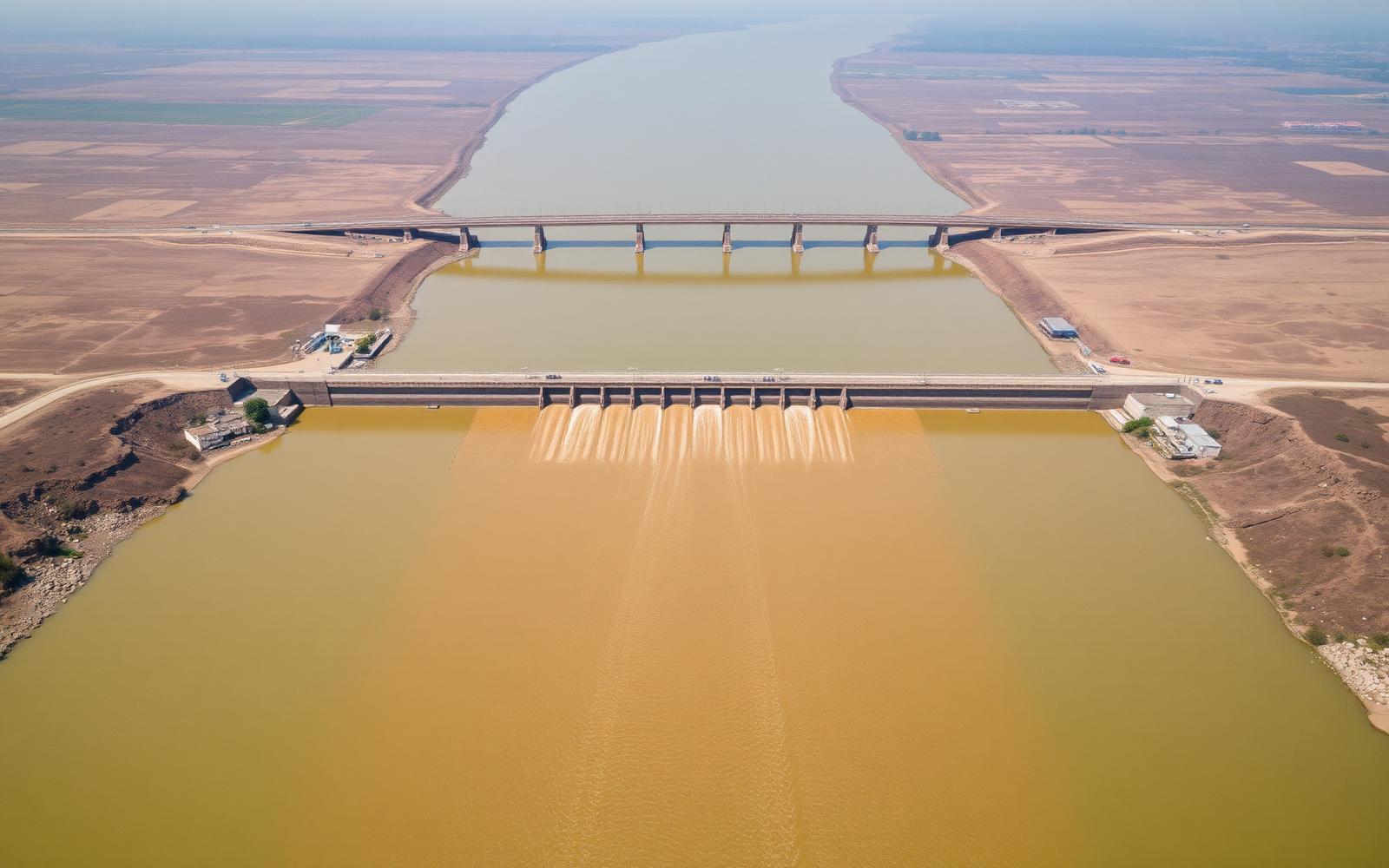
Barrage across a river with a line of gates
Fig. 2 Barrage headworks: diversion, pond level and silt exclusion
1948
Manufacturing Since
3 Tiers
Headworks · Canal Network · Farm Level
100%
Gates Trial-Assembled Before Dispatch
ISO 9001
Certified Quality System
System Chain

River to Root Zone

The irrigation chain in sequence — what each structure is for, what it demands from equipment, and where water control is installed.

01 Stage 01

Barrage & Headworks

PurposeRaise river level, divert the design discharge into the canal and pass floods safely.
EngineeringHigh seating head, flood loading, heavy silt, under-sluice scouring, long standing intervals.
Water ControlVertical lift gates, silt-excluder gates, stop logs, hoisting arrangements, trash screens.
Fabricated steel gatesTrash racksSpindles & headstocksEmbedded frames
02 Stage 02

Canal Head Regulator

PurposeAdmit the sanctioned discharge into the main canal and exclude silt and debris.
EngineeringAccurate opening control, low leakage past seals, gate stability under partial opening.
Water ControlSluice gates with calibrated hoist, trash racks, stop-log grooves for dry maintenance.
Sluice gatesPenstocksGear headstocksTrash racks
03 Stage 03

Main Canal & Cross Regulators

PurposeConvey water along the reach and hold upstream level so offtakes draw their design share.
EngineeringLevel holding within centimetres, silt deposition, long unattended service, bank access.
Water ControlCross regulator gates, escape gates, fall structures, canal drainage crossings.
Vertical lift gatesStop logsRising-stem spindlesWalkway gratings
04 Stage 04

Distributaries & Minors

PurposeDistribute the canal supply into smaller channels serving defined command areas.
EngineeringEquitable proportioning, resistance to tampering, operation by field staff without power.
Water ControlOfftake gates, head regulators for distributaries, escape and tail structures.
CI sluice gatesPenstock gatesLockable headstocks
05 Stage 05

Outlets & Watercourses

PurposeDeliver each farmer's turn (warabandi share) from the minor into a lined watercourse.
EngineeringConveyance loss control, seepage, weed and silt blockage, low-cost repeatable components.
Water ControlNakka valves, small penstocks, pipe outlets, culvert pipes and end caps.
Sluice valvesPVC / HDPE outletsCI & MS pipesSmall penstocks
06 Stage 06

Tubewells & Lift Irrigation

PurposeSupplement canal supply with groundwater, or lift water onto command above canal level.
EngineeringDuty point against variable water table, sand in the bore, surge on start and stop.
Water ControlPump isolation, non-return protection, air release, delivery line valves.
Turbine & centrifugal pumpsCheck valvesSluice valvesAir release valves
07 Stage 07

Drainage & Disposal

PurposeRemove surplus and saline water so waterlogging and salinity do not destroy the command.
EngineeringBrackish and aggressive water, backflow from the outfall, intermittent heavy-duty running.
Water ControlFlap gates against backflow, pump station isolation, screens ahead of every intake.
Flap gatesDrainage pumpsTrash screensSluice gates
Engineering Challenges

What Actually Fails in the Field

Ten recurring failure modes on canal and irrigation structures, and the design response each one requires.

F-01

Seal Leakage Under Head

A gate that passes water when closed wastes discharge continuously and erodes the downstream floor. Leakage usually starts at the seal seat, not at the leaf: distorted seat faces, worn rubber and a frame that was never grouted true.

Response ·Machined seat faces, replaceable seals, frames set with grout template
F-02

Spindle Buckling & Bending

Rising-stem spindles buckle when the closing thrust exceeds their slenderness limit, or bend when the leaf jams on one side. The gate then cannot be lifted at the exact moment a regulator setting must change.

Response ·Spindle sized for thrust and unsupported length, guided at intervals
F-03

Silt Abrasion

Indus water carries a heavy silt load. Abrasion wears seal seats, guide grooves and pump internals — first showing as increased leakage, then as loss of alignment and rising operating effort.

Response ·Stainless seal seats, hardfaced guides, generous corrosion/wear allowance
F-04

Seizure After Long Standing

Many gates are lifted twice a year. Between operations the stem thread corrodes, the nut galls and the guides pack with silt, so the gate refuses to move during a closure window that lasts days, not weeks.

Response ·Bronze stem nut, stainless stem, grease-packed headstock, periodic exercising
F-05

Corrosion & Coating Failure

Alternate wet and dry zones at the water line corrode fastest. Poor surface preparation makes any paint system fail early — the coating lifts, the section thins, and the leaf loses stiffness.

Response ·Blast cleaning to standard, epoxy or hot-dip galvanised systems, sacrificial thickness
F-06

Trash & Weed Blockage

Floating weed, plastic and crop residue choke intakes, block outlets and jam gate grooves. A blocked screen also raises differential head across the rack, which can collapse an under-designed one.

Response ·Trash racks designed for full differential head, rakeable bar spacing
F-07

Conveyance & Seepage Loss

Unlined watercourses and leaking outlet structures lose a large share of the delivered discharge before it reaches the field, and the loss falls hardest on tail-end farmers.

Response ·Tight nakka valves, pipe outlets, correctly bedded CI/HDPE conveyance
F-08

Backflow into Drains

When the outfall rises, water flows back through the drainage line and floods the area the system was built to protect. Flap gates that are warped or silted simply do not seat.

Response ·Rigid flap leaves, adjustable hinges, self-cleaning seat geometry
F-09

Pump Cavitation & Sand Wear

Lift and tubewell pumps run with a falling water table and sand in suspension. Insufficient NPSH and abrasive sand destroy impellers and bowls within a season.

Response ·Duty point verified against drawdown, wear-resistant impellers, strainers
F-10

Spare Part Obsolescence

Structures built decades ago carry gates for which no drawing survives. Imported replacements do not fit the embedded frame, and re-casting the whole structure is not an option.

Response ·Reverse-engineered parts made to a measured sample or site survey
REW Solutions

Equipment for Canal Duty

Only equipment relevant to irrigation and canal service is listed. Final selection is confirmed against your structure drawings, seating head and gate schedule.

Request Selection Support →
REGULATIONFabricated steel penstock gates in a canal regulator
Regulation

Penstock & Sluice Gates

Fabricated steel or cast iron vertical lift gates with machined seal seats, wedge blocks and a rising or non-rising spindle. The primary regulating element on almost every canal structure.
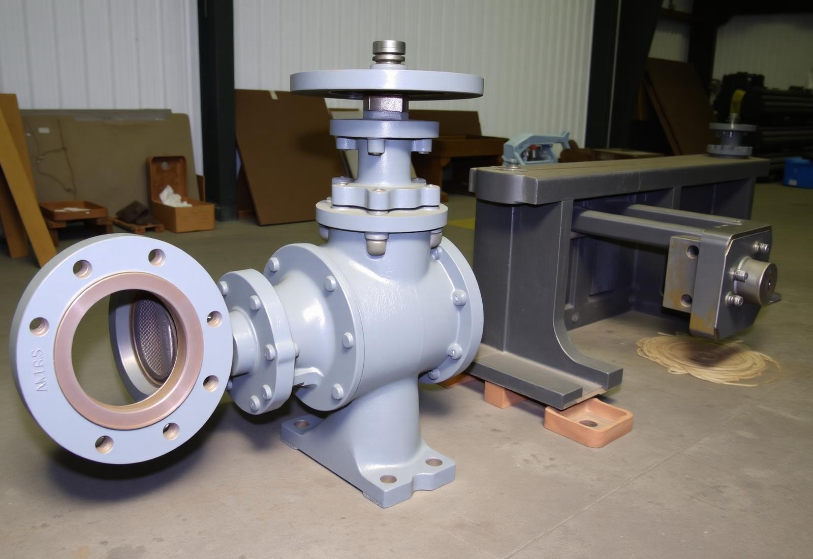
LocationHead regulators, cross regulators, distributary offtakes, escapes, drainage outfalls
AdvantagePositive shut-off under head, calibrated opening, field-replaceable seals and spindle
ConditionsSilt-laden canal water; seating and unseating head to project specification
Frame must be grouted true — a distorted frame cannot be corrected by the leaf
ISOLATIONCast iron flanged sluice valve with handwheel
Isolation

Sluice & Gate Valves

Flanged cast iron and carbon steel sluice valves for pipe-borne irrigation: outlet lines, tubewell delivery, lift mains and pressurised distribution to sprinkler and drip networks.
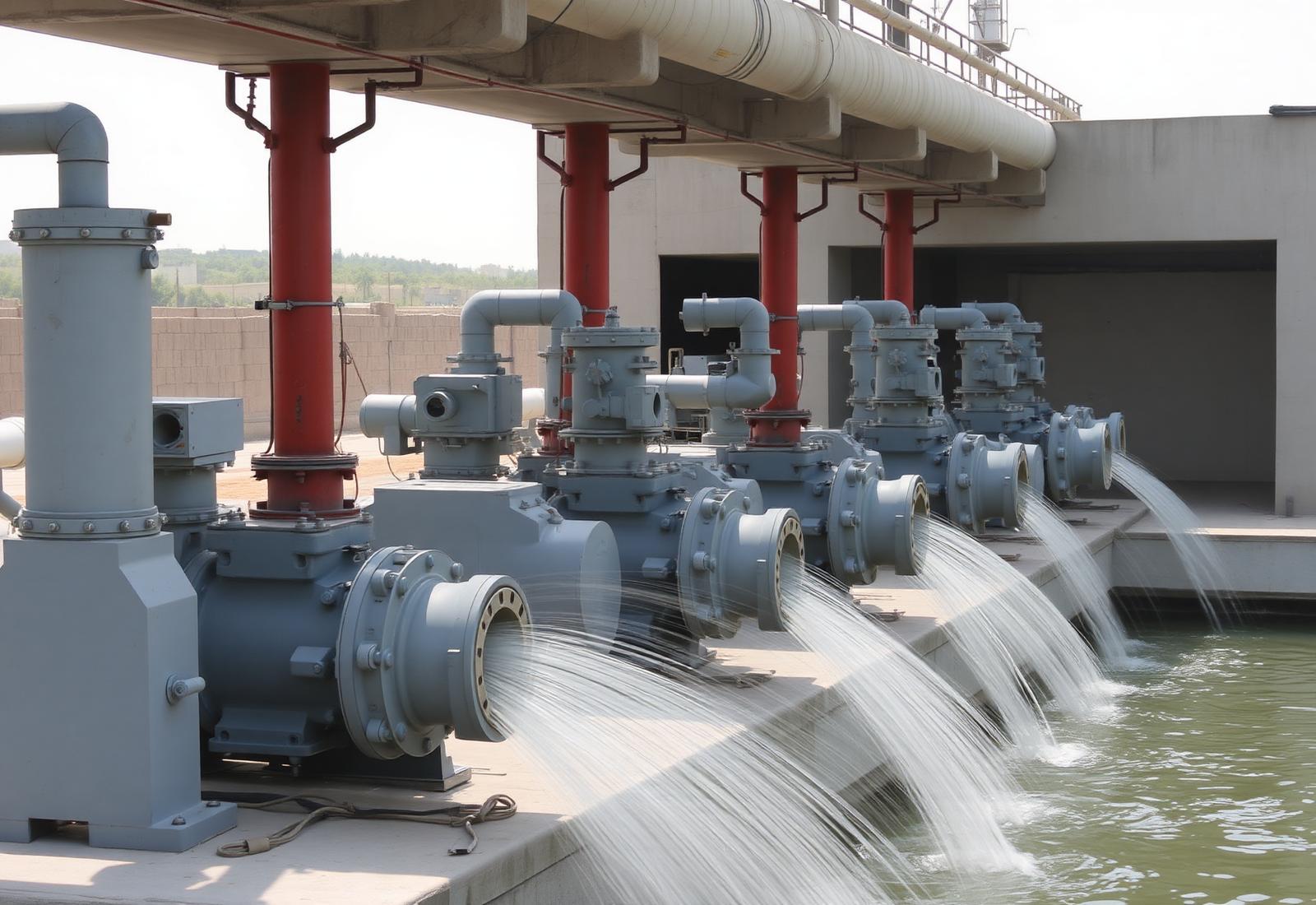
LocationTubewell discharge lines, pump manifolds, watercourse pipe outlets, farm nakkas
AdvantageFull-bore passage, low head loss, simple handwheel or key-top operation
ConditionsCanal and groundwater duty; resilient-seated options for gritty water
On/off duty only — throttling a sluice valve erodes the seat faces
PROTECTIONDrainage pump station discharging into an outfall channel
Protection

Check & Flap Valves

Non-return protection on pump delivery lines and flap gates at drainage outfalls, preventing reverse flow into the channel or back through the pump when the set stops.
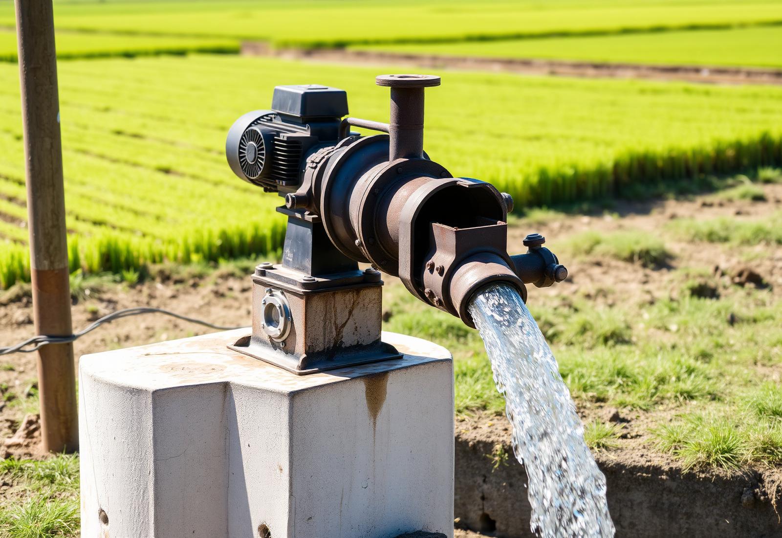
LocationDownstream of every irrigation and drainage pump; outfall and culvert ends
AdvantageAutomatic operation with no power or attendance; protects pump and command area
ConditionsIntermittent duty, brackish drainage water, floating debris at the outfall
Oversized check valves chatter — size on minimum operating flow
PUMPINGTubewell pump discharging into a concrete watercourse
Pumping

Irrigation & Drainage Pumps

Centrifugal, vertical turbine and mixed-flow pumps for tubewells, lift irrigation schemes and surface drainage stations, supplied with matched valves, strainers and spare parts.
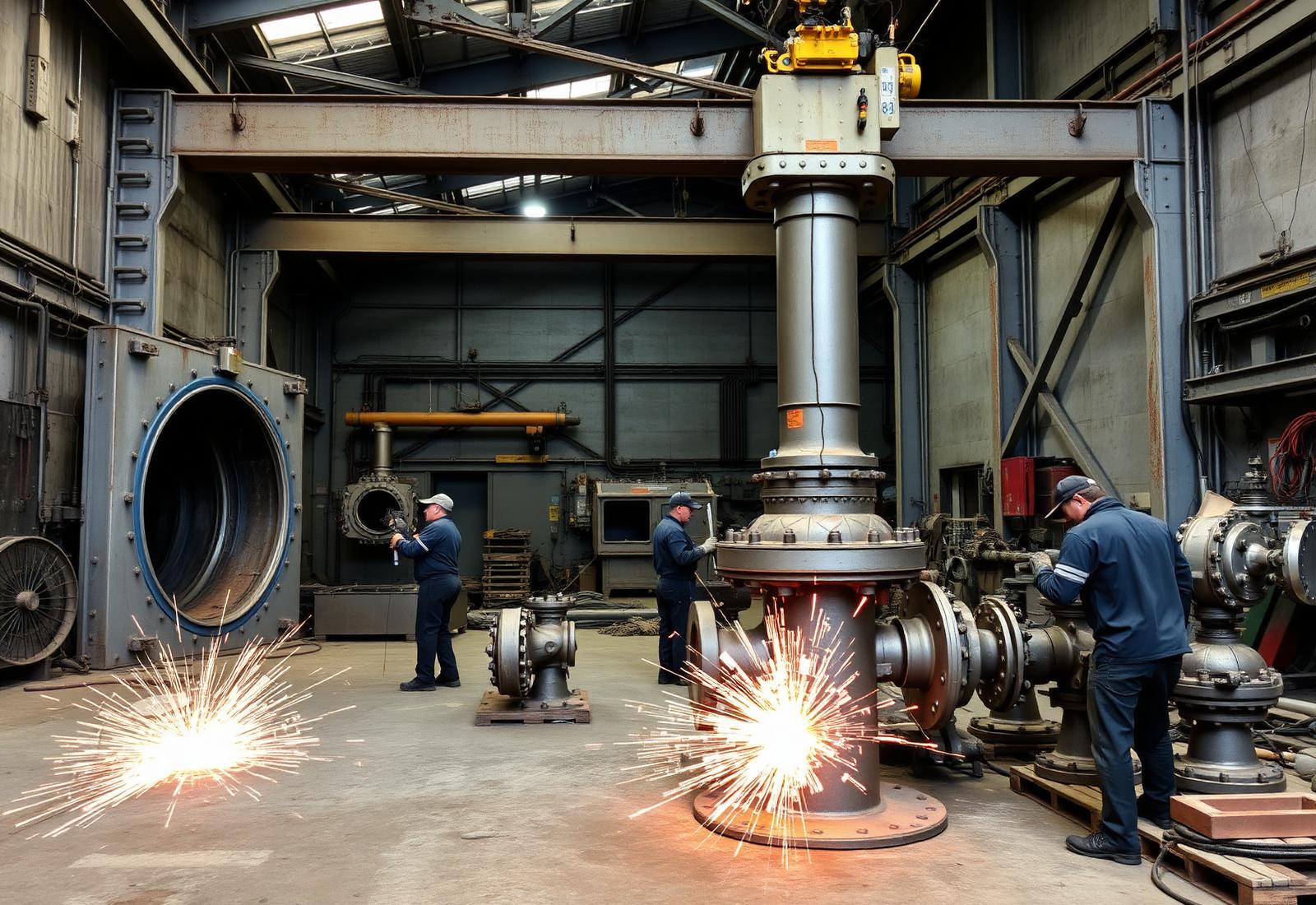
LocationTubewell heads, lift stations, drainage sumps, canal-side booster sets
AdvantageSelected against the actual duty point and drawdown, not against nameplate flow
ConditionsSandy groundwater, seasonal water-table variation, single-phase and diesel drives
Confirm NPSH available at the lowest expected water level
SCREENINGFabrication of trash racks and gate frames in the workshop
Screening

Trash Racks & Screens

Welded bar screens and rakeable trash racks ahead of intakes, pump sumps and siphon entries, designed for the full differential head that occurs when the rack blinds with weed.
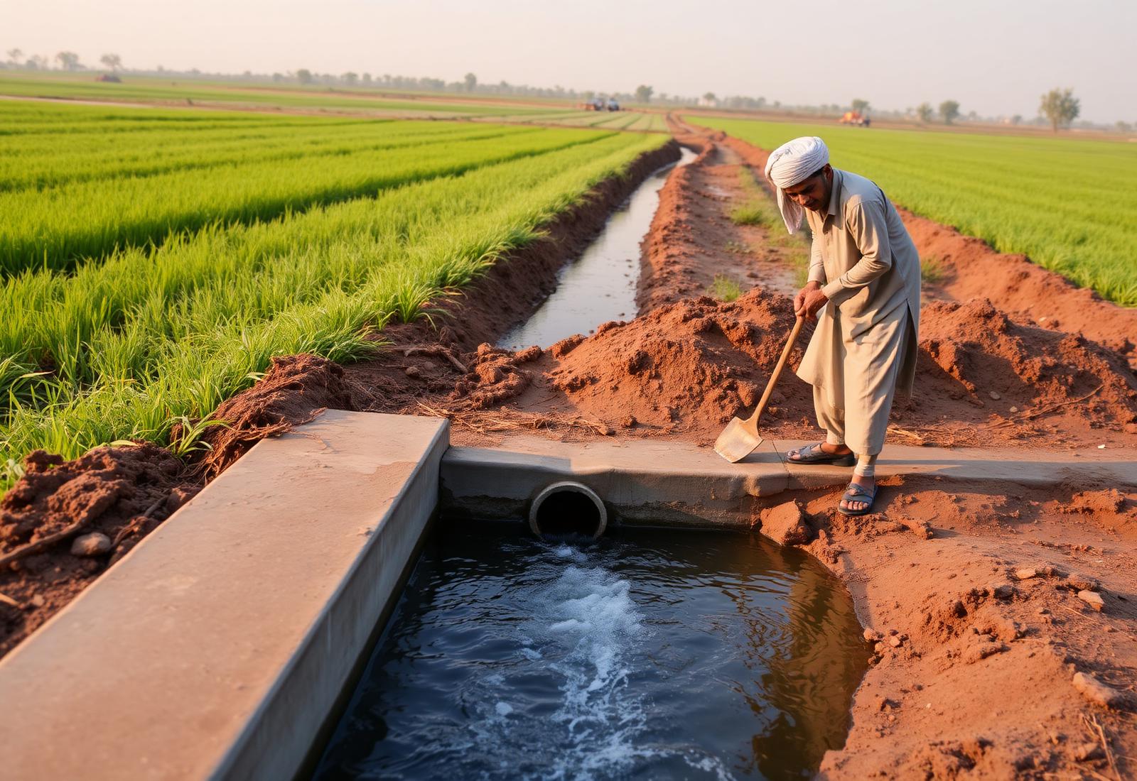
LocationCanal intakes, pump station forebays, siphon and culvert entries, outlet structures
AdvantageProtects gates and pumps from debris; bar spacing matched to the equipment behind it
ConditionsHeavy floating weed load; manual or mechanical raking access provided
A rack designed only for clean-flow head will fail when it blinds
CONVEYANCELined watercourse delivering water to a field
Conveyance

Pipes, Outlets & Air Valves

MS and CI pipes, HDPE pipe and fittings, pipe outlets, nakka valves and air release valves for lined watercourses, buried conveyance and pressurised farm distribution.

LocationWatercourse improvement works, buried mains, siphons, sprinkler and drip headers
AdvantageCuts seepage and operational loss between the outlet and the crop root zone
ConditionsBuried service, low pressure gravity flow or pumped pressurised distribution
Air release valves at every summit — trapped air throttles a buried line
Application Map

Where Each Product Is Installed

Hover a node on the schematic to see the equipment installed at that point in the irrigation chain.

Flow →
Barrage
Headworks · Stage 01
Regulation Points

Sluice and penstock gates at every structure that sets a discharge or holds a level.

Isolation Points

Sluice valves on tubewell, lift and pipe-borne conveyance lines.

Protection Points

Check valves after pumps and flap gates at every drainage outfall.

Screening Points

Trash racks ahead of intakes, siphons and pump sumps.

Technical Reference

Irrigation Equipment Specification Sheet

Reference data for design, execution and procurement teams. Project-specific values are confirmed at quotation stage against your drawings and BOQ.

Irrigation & Canal Equipment · Reference Data DOC · IRR-REF-2026
Product ScopePenstocks and sluice gates, flap gates, stop logs, trash racks, sluice and check valves, air release valves, MS/CI/HDPE pipe, pumps, spares
Structures ServedBarrages and headworks · head and cross regulators · falls and escapes · distributaries, minors and outlets · watercourses · drainage and lift stations
Gate TypesFabricated steel vertical lift, cast iron sluice, wall-mounted and channel-mounted, weir (top-sealing) gates, flap gates, stop-log sets
Typical Gate Sizes300 × 300 mm up to 3000 × 3000 mm and larger to drawing; multiple bays supplied as matched sets
Seating HeadDesigned to project head; typical canal duty up to 10 m seating head with unseating head to specification
Body / Leaf MaterialsStructural steel plate and sections, cast iron, stainless steel 304 / 316 where water chemistry requires
Seal & Seat MaterialsStainless steel seal seats, rubber (EPDM / neoprene) J-seals and music-note seals, bronze wedge and guide faces
Spindle & HoistingRising or non-rising stainless / carbon steel spindles, bronze stem nut, handwheel, gear headstock, geared bevel or electric actuator
Design ReferencesIS 3042 (sluice gates), IS 5620 (hoisting), IS 11228 (trash racks), BS, AWWA C560/C561 concepts and client project specifications
ValvesSluice / gate, check, butterfly, air release and pressure reducing valves — flanged to ANSI, BS or DIN drilling
PumpsCentrifugal, vertical turbine, mixed-flow and dewatering pumps selected against duty point, drawdown and NPSH available
TestingTrial assembly of leaf and frame, leakage check against seal seats, hydrostatic shell and seat test on valves, performance test on pumps
Surface ProtectionBlast cleaning, epoxy primer with high-build coal-tar-free epoxy finish, or hot-dip galvanising to project specification
DocumentationApproved fabrication drawings, material test certificates, dimensional report, test records, installation and O&M instructions
Installation SupportFrame setting templates, anchor and grouting details, supervision of erection and commissioning on request
CertificationISO 9001:2015 quality management system; PSQCA marked products where applicable
Manufacturing OriginLahore, Pakistan — Rehman Engineering Works, established 1948
Manufacturing

A Gate Is Only as Good as Its Seat Face

A canal gate is installed once and expected to work for thirty years, operated by hand, under silt and head. Whether it still seals in year fifteen is decided in the fabrication bay — in plate cutting, weld sequence, seat machining and trial assembly.

01

Drawing & Approval

Gate schedule, seating head, structure openings and hoist arrangement converted into fabrication drawings for client approval before cutting.

02

Material Preparation

Plate and section cut to size, edges prepared, castings inspected; heat numbers and mill certificates recorded against the job.

03

Welding & Distortion Control

Controlled weld sequence on leaf stiffeners and frames so the sealing plane stays flat — distortion here cannot be corrected later.

04

Seat Machining

Stainless seal seats fitted and machined true; guide and wedge faces finished so contact pressure is even across the full seal length.

05

Trial Assembly

Leaf, frame, seals, wedges, spindle and headstock assembled in the shop; travel, wedging action and operating effort verified.

06

Testing

Leakage check against the seal line, hydrostatic shell and seat tests on valves, and performance testing on pumps before release.

07

Coating, Marking & Dispatch

Blast cleaning, epoxy or galvanised protection, match-marking of bays, packing with anchor bolts, templates and documentation.

Fabrication of steel gates and valve bodies in the workshop
Workshop · LHR Gate frames and valve bodies in fabrication and assembly
Quality Assurance

Proven Before It Reaches the Structure

Inspection is built into the route card, not added at the end. Each stage has a hold point, and no gate or valve is released without its record.

Hold Point 1

Drawing Approval

Gate schedule and structure openings confirmed against site dimensions before cutting.

Hold Point 2

Incoming Material

Plate, casting and seal material verified against mill certificates and heat numbers.

Hold Point 3

Weld & Flatness Check

Weld visual inspection and flatness of the sealing plane after fabrication and stress relief.

Hold Point 4

Trial Assembly

Full assembly of leaf, frame, seals and hoist; travel and operating torque recorded.

Hold Point 5

Pressure & Leakage Test

Hydrostatic shell and seat testing on valves; seal-line leakage check on gates.

Hold Point 6

Coating & Documentation

Coating thickness measured, match-marking checked, test certificates issued with dispatch.
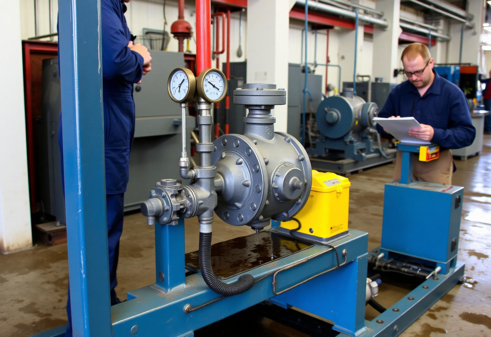
QA · TEST BAY Hydrostatic test bench with a valve under pressure
Hydrostatic Test Bench · Pressure Hold
Why Irrigation Engineers Work With REW

Six Practical Reasons

01

Built for This System

Gates, valves and screens are designed against the seating head, silt load and manual operation that Pakistani canal structures actually see — not against a catalogue duty from a different climate.

02

Made to Your Drawing

Every structure is different. Leaf sizes, frame embedment, wall thickness and hoist arrangement are made to the approved drawing, so the gate fits the opening that already exists in concrete.

03

Public-Sector Experience

Familiar with irrigation department, WAPDA, WASA and contractor procedures: BOQ item interpretation, inspection at works, third-party testing, and documentation that survives audit.

04

Delivery to Remote Sites

Manufacturing in Lahore means short lead times and consignments that reach a site in Sindh, south Punjab or Balochistan without an import cycle or a foreign-exchange approval.

05

Rehabilitation Capability

Decades-old gates with no surviving drawings are reverse-engineered from a site survey or a worn sample — spindles, nuts, seals and complete leaves that fit the original embedded frame.

06

Maintainable by Field Staff

Standard fasteners, replaceable seals, greasable headstocks and simple wedge adjustment mean routine maintenance is done during the annual closure with the tools the beldar already has.

Technical FAQ

Engineering Questions

Questions most often raised by irrigation departments, consultants and contractors working on canal and watercourse schemes.

A penstock (or sluice) gate closes a rectangular or circular opening in an open channel or wall — it is a structural component set into concrete and operated by a spindle and headstock. A sluice valve is a pipeline component with flanged ends, installed in a pressurised or gravity pipe. Canal regulators use gates; tubewell and watercourse pipe lines use valves.
Seating head presses the gate leaf onto its seals — the design condition for almost every canal gate. Unseating head pushes the leaf away from the seat, and the seals must be retained mechanically or they will be blown out. If your structure can ever be flooded from the downstream side, state the unseating head in the enquiry; it changes the seal design, the wedge arrangement and the frame.
Cast iron sluice gates suit smaller, standard openings where the head is moderate and a compact, corrosion-tolerant body is preferred. Fabricated steel gates suit larger openings, non-standard sizes, higher heads and situations where the leaf must be stiffened for a specific span. Above roughly 1200 mm square, fabricated steel is usually the economical answer.
For gates operated occasionally by field staff, a rising stainless steel spindle with a bronze stem nut in a greased pedestal headstock is the most reliable arrangement. Where the lift is high, a bevel-gear headstock reduces the effort to a level one person can apply. The spindle must be sized for buckling over its unsupported length, and guided where that length is long.
Almost always because the embedded frame is out of plane. If the frame is grouted without a template, or the concrete moves during pour, the seal line is no longer flat and the leaf cannot contact it evenly. The fix is procedural: set the frame with the leaf and a template in place, grout in stages, and check the seal line before the second pour.
Bar spacing is set by what must be kept out of the equipment behind the rack — pump impeller passage or gate groove clearance. The structural design is governed by the differential head when the rack is fully blinded with weed, not by the clean-flow head loss. A rack designed only for clean flow will collapse the first time it chokes during a weed season.
Yes. This is routine work. A site survey of the embedded frame, groove dimensions, invert level and hoist centre-line is enough to produce fabrication drawings for approval. Where a component such as a spindle, stem nut or seal can be removed, a sample lets us match the original exactly or upgrade the material where the failure history suggests it was marginal.
For the alternate wet-and-dry zone at the water line, blast cleaning followed by a two-coat high-build epoxy system gives the best service life. Hot-dip galvanising suits smaller gates, screens and fasteners. Whatever the system, surface preparation decides its life — paint applied over mill scale will fail regardless of the product specified.
Conveyance losses between the outlet and the field in unimproved watercourses are widely estimated at 30–40% of the delivered discharge, mostly to seepage and to spillage at unregulated nakkas. Lining plus properly seated pipe outlets and nakka valves recovers a large part of that, which is why watercourse improvement programmes have concentrated on exactly these components.
Select against the duty point at the lowest expected water level, not the standing level. Provide the static lift at maximum drawdown, the delivery pipe size and length, the required discharge and the available power supply. Sand content matters too — abrasive groundwater calls for wear-resistant impellers and a strainer, otherwise efficiency drops within one season.
Air collects at every summit in a buried line. A trapped air pocket reduces the effective bore, throttling the discharge for no visible reason, and can cause damaging pressure surges when it is finally swept along. Air release valves at each summit and at long ascending runs prevent both, and vacuum relief protects the pipe when the line drains.
A flap gate — a hinged leaf that opens with outward flow and closes when the outfall level rises. The failure modes are warping of the leaf, silt on the seat and a seized hinge, so specify a rigid leaf, adjustable hinge and a seat geometry that sheds silt, and include the flap gates in the annual maintenance round.
The gate schedule (size, quantity, type), seating and unseating head, invert and operating floor levels, structure drawings or opening dimensions, hoisting preference (handwheel, gear headstock or actuator), coating requirement, applicable standard or department specification, and the inspection and documentation scope. For pumps, add duty point, drawdown and power supply.
Exercise every gate through its full travel at least once a season — the single most effective measure against seizure. Grease the stem and headstock, check and adjust wedges, inspect and replace seals when leakage rises, clear silt from grooves, and record the operating effort. A rising operating effort is the earliest warning that guides or wedges need attention.
Project Enquiry

Send Us the Structure Data

Share your BOQ, gate schedule, structure drawings or canal cross-section and our engineering team will confirm gate sizes, seating arrangement, hoist duty, materials and testing scope. For repair work, a photograph of the existing gate frame or worn spindle is usually enough to begin.

Direct Lines

Route your enquiry to the right desk and you will get an engineering answer, not a sales script.

Enquiries

Gate, penstock and valve selection, head and seating queries, technical clarifications

Procurement

BOQ rates, budgetary and firm quotations, delivery to site, documentation scope

Maintenance

Spindles, seals, hoist gearboxes, rehabilitation of existing gates

Facility · Rehman Engineering Works
Lahore, Pakistan · Manufacturing since 1948
Your details are only used to respond to this enquiry.