Rehman Plaza, Sanda Khurd, Bund Road, Lahore, Pakistan

Oil & Gas

Oil & Gas Industry Solutions — REW | Valves, Pumps & Flow Control Since 1948
Rehman Plaza, Sanda Khurd, Bund Road, Lahore, Pakistan
Home/ Industries/ Oil & Gas
REW Industries · Oil & Gas

Flow Control for
Hydrocarbon Service

Upstream Systems
Midstream Pipelines
Downstream Refining
Storage Terminals
Compressor Stations
Sour Service Ready
Up · Mid · Down

Hydrocarbon systems do not tolerate approximate engineering. Every isolation point, every pressure boundary and every sealing face carries pressure, temperature and hazard consequences. REW designs and manufactures valves, pumps and spare parts for wellhead gathering lines, transmission pipelines, compressor stations, refineries, LPG plants and storage terminals — built to withstand the pressures, temperatures and sour-service conditions found across Pakistan's energy infrastructure.
Rehman Engineering Works · Lahore, Pakistan Manufacturing since 1948 ISO 9001:2015 Certified
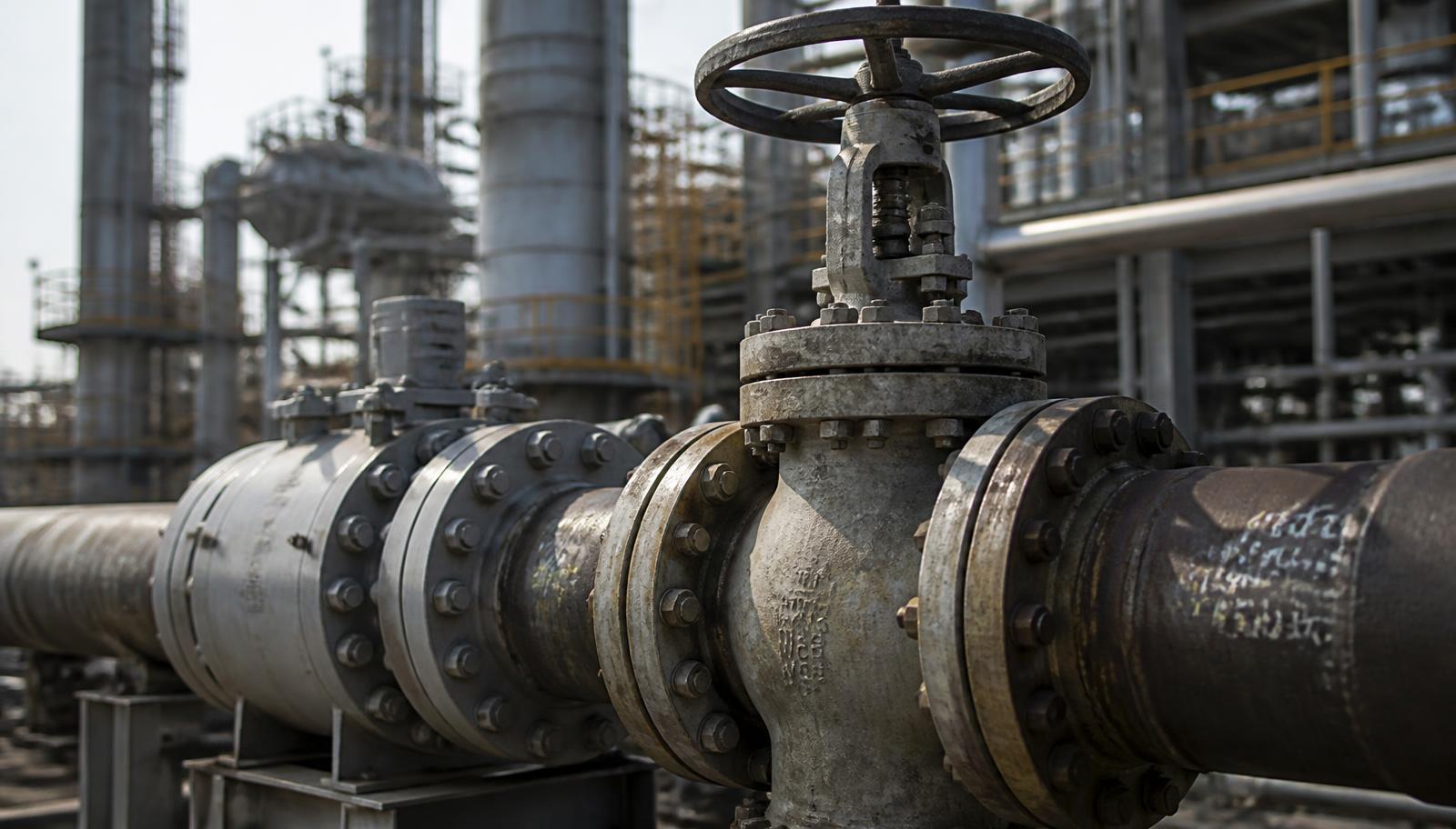
Process isolation valve assembly REF · O&G-2026 Process Isolation Point
Service Ledger
Flanged Gate & Ball Valve Assembly · Refinery Unit
ISO 9001:2015 Certified Valves · Pumps · Spare Parts
Wellhead to Refinery Full Chain Coverage
Hydrostatic Shell & Seat Testing
Lahore, Pakistan · Since 1948
1948
Manufacturing Since
3 Sectors
Upstream · Midstream · Downstream
100%
Pressure Tested Before Dispatch
ISO 9001
Certified Quality System
Service Sectors · Up · Mid · Downstream Design References · API · ANSI · BS · DIN Testing · Hydrostatic & Seat Manufacturing · Since 1948 NACE MR0175 Sour Service Fire-Safe Design
Scroll
Industry Overview

Engineering for Pressure, Heat and Hazard

Pakistan's oil and gas system runs from producing fields in Sindh, Balochistan and the Potohar region, through thousands of kilometres of transmission and distribution pipeline, into refineries, LPG plants, power stations and coastal storage terminals. Every element of that chain depends on equipment that holds pressure, isolates reliably and can be maintained without extended shutdown.

Upstream equipment faces sand-laden multiphase flow, high wellhead pressure and, in many fields, hydrogen sulphide. Material hardness limits, trim selection and seal design govern service life more than nominal pressure rating.

Midstream transmission and gathering systems demand tight shut-off for pigging, sectionalising and emergency isolation, plus surge control that protects the line from transient overpressure during rapid valve closure or compressor trip.

Downstream refineries and terminals operate a wide temperature range — from cryogenic LPG service to hot residue lines — with hydrocarbon fluids that are flammable, sometimes corrosive, and often handled under continuous production. Equipment here is specified for fugitive emission control, fire-safe integrity and predictable maintenance intervals.

Across all three, the practical constraints are the same: correct material selection, dimensional accuracy at sealing faces, documented pressure testing, and the availability of spare parts that fit the installed base. Those are manufacturing problems before they are procurement problems.

Engineers verifying isolation philosophy
Fig. 1 Field verification of isolation philosophy against P&ID
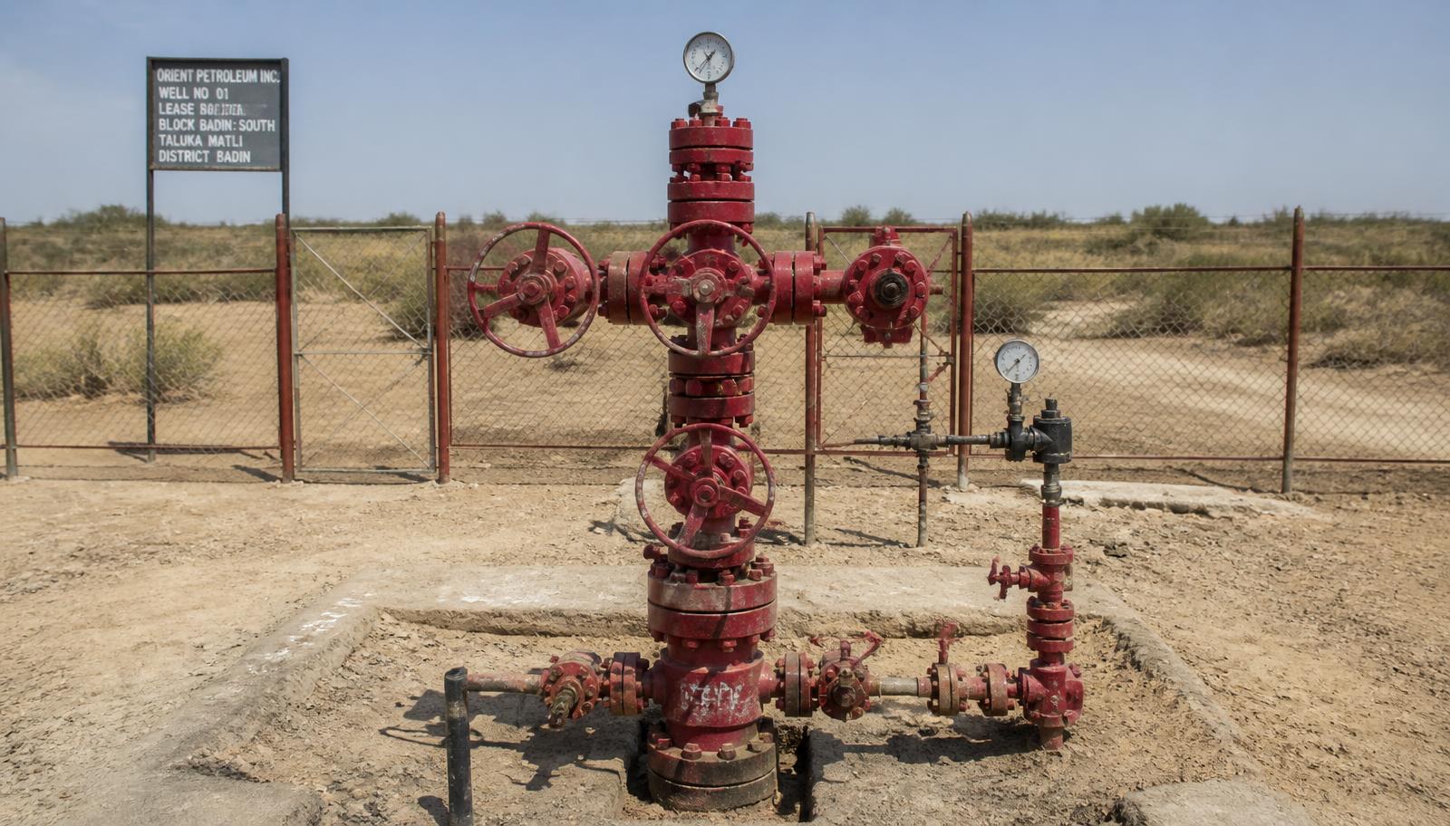
Wellhead isolation assembly
Fig. 2 Wellhead assembly: master, wing and swab isolation
1948
Manufacturing Since
3 Sectors
Upstream · Midstream · Downstream
100%
Pressure Tested Before Dispatch
ISO 9001
Certified Quality System
Process Chain

Wellhead to End User

The hydrocarbon chain in sequence — what each stage is for, what it demands from equipment, and where flow control is installed.

01 Stage 01

Wellhead & Gathering

PurposeBring produced fluid to surface under control and route it to the gathering manifold.
EngineeringHigh shut-in pressure, erosive sand, possible H₂S. Hardness-controlled materials.
Flow ControlPositive isolation, double block capability, throttling of choke flow.
Gate valvesBall valvesCheck valvesNeedle & gauge valves
02 Stage 02

Separation & Processing

PurposeSeparate gas, oil and water; remove condensate, H₂S and moisture before transport.
EngineeringVessel level and pressure control, corrosion allowance, chemical injection.
Flow ControlRegulating duty, tight seat leakage class, drain and vent isolation.
Globe valvesBall valvesDosing pumpsStrainers
03 Stage 03

Transmission Pipeline

PurposeMove gas or liquid hydrocarbon over long distance at high pressure.
EngineeringFull-bore passage for pigging, buried-service protection, surge management.
Flow ControlSectionalising isolation, bypass, blowdown, pig launcher/receiver isolation.
Full-bore ball valvesGate valvesCheck valves
04 Stage 04

Compressor / Pump Station

PurposeRestore pressure lost to friction and lift the fluid to the next station.
EngineeringVibration, cyclic loading, anti-surge control, machine protection.
Flow ControlSuction/discharge isolation, non-return protection, recycle and relief paths.
Process pumpsCheck valvesGate valvesY-strainers
05 Stage 05

Refinery & Process Plant

PurposeConvert crude and raw gas into usable products through distillation and treatment.
EngineeringWide temperature band, thermal cycling, flammable inventory, unit turnaround windows.
Flow ControlUnit isolation, throttling, emergency shutdown, drain and steam-out points.
Gate · Globe · Ball · Check valvesFeed & transfer pumps
06 Stage 06

Storage Terminal

PurposeHold product between production and distribution, and load road or rail tankers.
EngineeringTank farm segregation, bund isolation, overfill protection, vapour control.
Flow ControlTank inlet/outlet isolation, manifold routing, loading arm shut-off.
Ball valvesGate valvesTransfer pumpsCheck valves
07 Stage 07

Distribution & End User

PurposeDeliver gas or product to industry, power plants and consumers at usable pressure.
EngineeringPressure reduction stages, metering accuracy, public-safety isolation.
Flow ControlEmergency shut-off, metering skid isolation, service line valves.
Ball valvesGlobe valvesStrainersSpare parts
Engineering Challenges

What Actually Fails in Service

Ten recurring failure modes in hydrocarbon systems, and the design response each one requires.

F-01

Pressure Containment

Pressure boundary integrity depends on wall thickness, casting soundness and bolted-joint design — not on rating stamp alone. Porosity in a body casting can pass visual inspection and fail under cyclic load.

Response ·Controlled casting, 1.5× design pressure shell test
F-02

Surge & Water Hammer

Rapid closure of a large isolation valve or a compressor trip creates a transient pressure wave that can exceed static design pressure and damage flanges, supports and instrumentation.

Response ·Controlled closure rate, correct check valve selection
F-03

Sour Service (H₂S)

Wet H₂S causes sulphide stress cracking in high-hardness steels. Failures are sudden and occur well below yield strength, often at welds and hardened trim.

Response ·NACE MR0175-aligned material and hardness control
F-04

Erosion & Sand Cut

Sand-laden flow erodes seat faces and body throats, first showing as passing isolation and later as through-wall loss at the throttling point.

Response ·Hardfaced trim, full-bore geometry, no partial throttling on gate valves
F-05

Corrosion & CO₂

Wet CO₂ produces localised pitting at flow disturbances; external corrosion attacks buried and coastal installations where coating is damaged.

Response ·Material grade selection, corrosion allowance, epoxy coating
F-06

Fire Safety

Soft-seated valves lose their sealing element in fire. Without a secondary metal seat the valve cannot isolate the very inventory feeding the fire.

Response ·Fire-safe design concept: secondary metal seat, graphite packing
F-07

Fugitive Emissions

Stem packing is the dominant leak path on process valves. Leakage is a product loss, an emissions liability and a safety exposure at the same time.

Response ·Live-loaded graphite packing, fine stem surface finish
F-08

Valve Seizure

Valves left in one position for years gall, scale and seize. The failure is discovered during an emergency, which is the worst possible moment.

Response ·Corrosion-resistant stem/nut pairing, partial-stroke exercising
F-09

Spare Part Availability

Imported spares for legacy equipment arrive late and often obsolete. Extended lead time converts a small defect into a production loss.

Response ·Locally manufactured, dimensionally matched replacement parts
F-10

Traceability Gaps

Without material certificates and test records, a component cannot be defended in a failure investigation or accepted in an audited plant.

Response ·Heat-number traceability, test certificate with every dispatch
REW Solutions

Equipment for Hydrocarbon Duty

Only equipment relevant to oil and gas service is listed. Final selection is confirmed against your line list, fluid data and design conditions.

Request Selection Support →
ISOLATIONGate Valves
Isolation

Gate Valves

Full-bore straight-through isolation with minimal pressure drop. Used where the valve stays fully open or fully closed for long periods and unrestricted flow area matters.
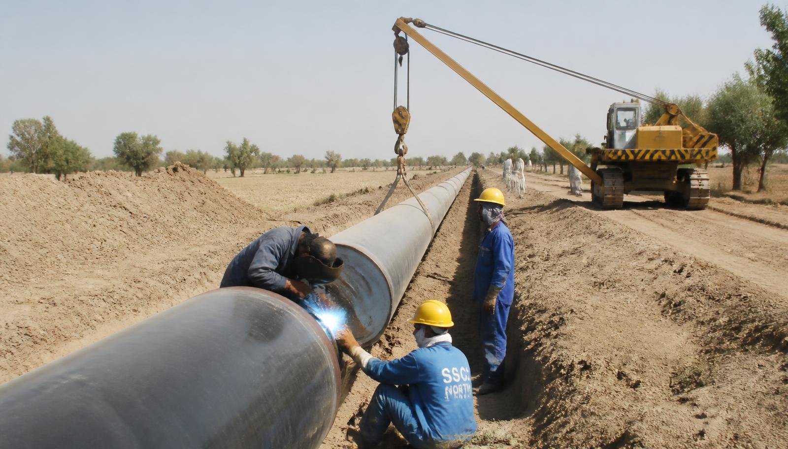
LocationPipeline sectionalising, pump and vessel isolation, tank outlets, unit battery limits
AdvantageLow head loss, bidirectional sealing, pig-passable in full-bore configuration
ConditionsClean to lightly contaminated hydrocarbon liquid and gas; on/off duty only
Not suitable for throttling — partial opening erodes seat and disc faces
QUICK SHUT-OFFBall Valves
Quick Shut-Off

Ball Valves

Quarter-turn isolation with tight shut-off and fast operation. The default choice for gas transmission, emergency shutdown points and manifold routing.
LocationTransmission mains, pig traps, metering skids, terminal manifolds, ESD points
AdvantageBubble-tight seating, rapid operation, full-bore flow path, actuator-ready stem
ConditionsGas and liquid hydrocarbon service; fire-safe and anti-static features on request
Closure speed must be matched to line surge analysis
REGULATINGGlobe Valves
Regulating

Globe Valves

Throttling and regulating duty where flow must be trimmed rather than simply stopped. Seat geometry is designed for controlled pressure drop across the plug.
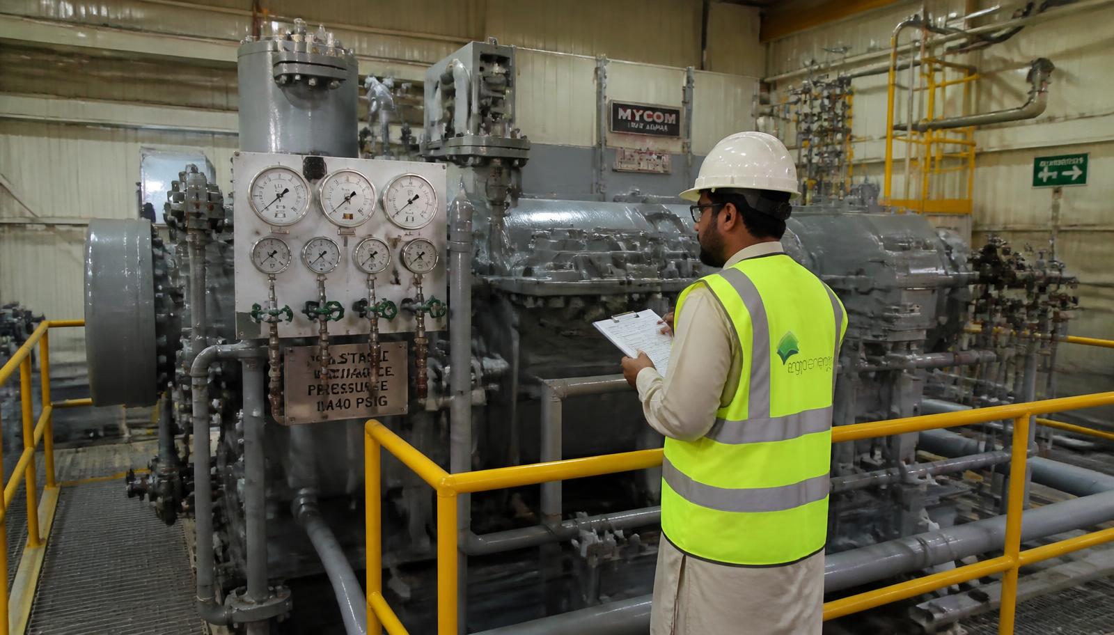
LocationVessel level and pressure control lines, bypass loops, steam and condensate service
AdvantageStable regulation, replaceable trim, predictable characteristic curve
ConditionsContinuous throttling; hardfaced trim available for erosive service
Higher pressure loss than gate or ball designs — size for the duty, not the line
PROTECTIONCheck Valves
Protection

Check Valves

Automatic reverse-flow prevention protecting pumps, compressors and upstream sections. Swing and lift patterns are selected against expected flow velocity and reversal rate.
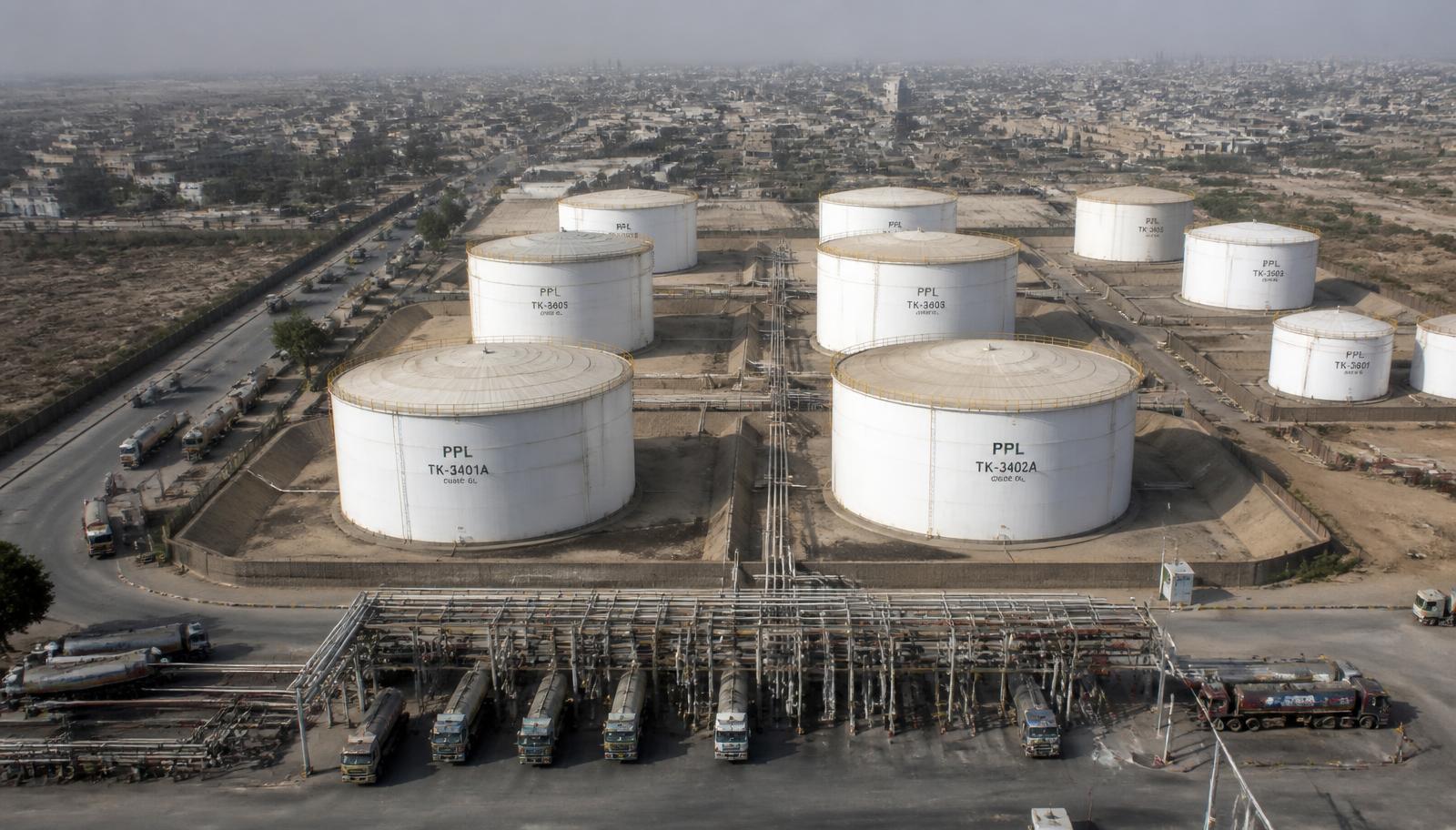
LocationPump and compressor discharge, manifold tie-ins, tank fill lines
AdvantageNo external power or operator action; protects rotating equipment on trip
ConditionsSized for minimum flow velocity to keep the disc stable and avoid chatter
Oversizing causes disc flutter and premature hinge pin wear
PUMPINGProcess and Transfer Pumps
Pumping

Process & Transfer Pumps

Centrifugal, multi-stage and gear pumps for product transfer, boiler feed, circulation and loading duty, supplied with the mechanical seal arrangement suited to the fluid.
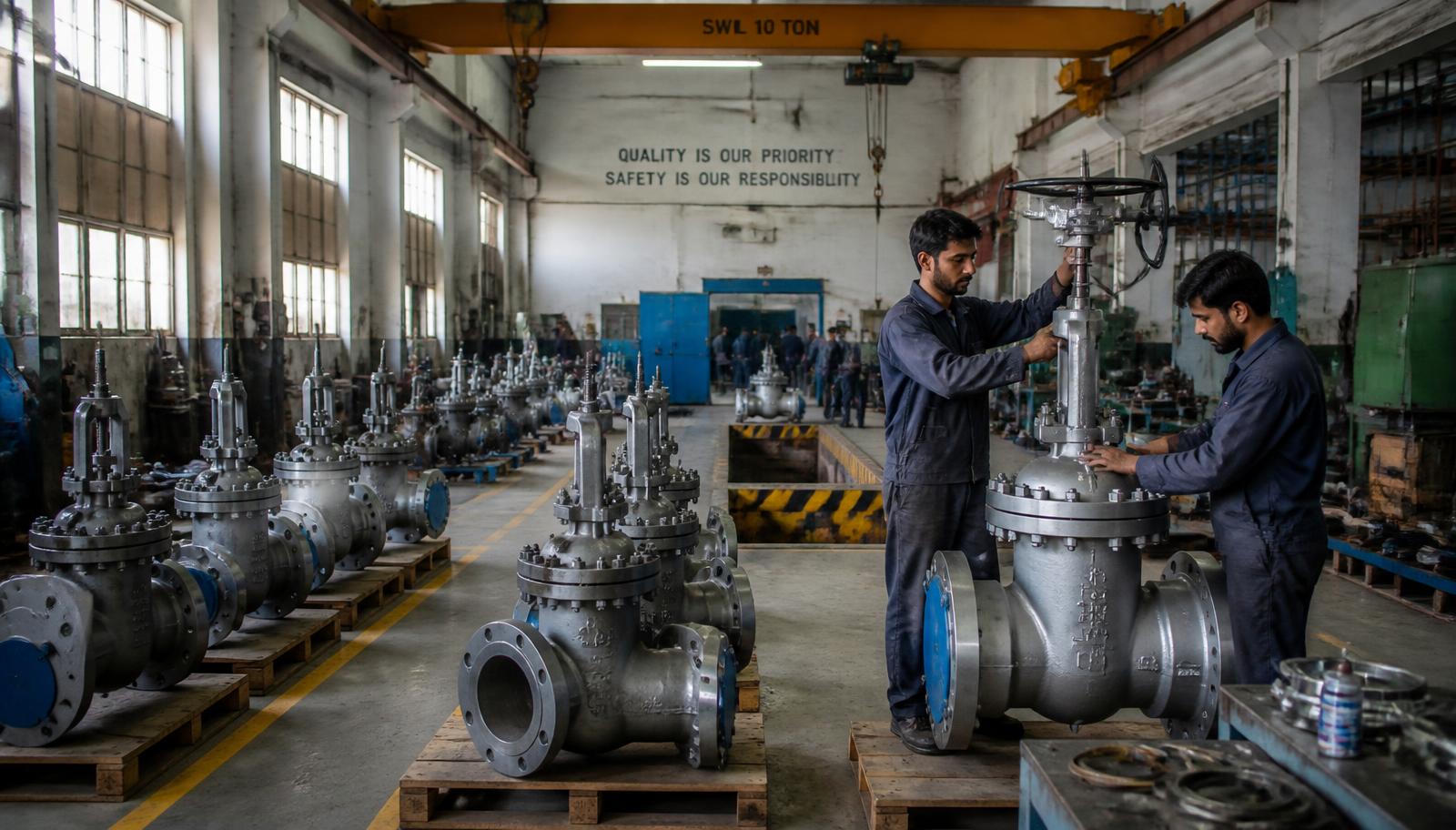
LocationTerminals, tank farms, refinery utility and transfer lines, loading gantries
AdvantageDynamically balanced rotating parts, performance-tested before dispatch
ConditionsSelected against duty point, NPSH available, fluid viscosity and temperature
Provide the system curve, not just flow and head, for accurate selection
SUSTAININGSpare Parts and Rebuild Kits
Sustaining

Spare Parts & Rebuild Kits

Discs, seats, stems, bonnets, gaskets, packing sets, impellers, shafts, sleeves and bearing housings — manufactured to match installed equipment dimensions.

LocationPlant maintenance stores, turnaround kits, strategic spares holding
AdvantageLocal manufacture removes import lead time on shutdown-critical items
ConditionsReverse-engineered from sample part, original drawing or measured dimensions
Send the worn part or a dimensioned sketch for the fastest quotation
Application Map

Where Each Product Is Installed

Hover a node on the schematic to see the equipment installed at that point in the hydrocarbon chain.

Flow →

Wellhead

Hover a node to view installed equipment.
Isolation Points

Gate and ball valves at battery limits, tank connections and pipeline sections.

Regulating Points

Globe valves on control, bypass and utility lines.

Protection Points

Check valves downstream of every pump and compressor.

Pumping Points

Transfer and feed pumps with matched spare part inventory.

Technical Reference

Oil & Gas Specification Sheet

Reference data for engineering and procurement teams. Project-specific values are confirmed at quotation stage.

Oil & Gas Equipment · Reference Data DOC · OG-REF-2026
Product ScopeGate · Globe · Ball · Check valves, process and transfer pumps, spare parts and rebuild kits
Sectors ServedUpstream production · Midstream transmission · Downstream refining, terminals and distribution
Typical Body MaterialsCast iron, carbon steel (WCB), low-temperature carbon steel, stainless steel 304 / 316, bronze
Typical Trim Materials13% Cr stainless, hardfaced (Stellite-type) overlay, SS 316, bronze — selected against fluid and duty
Sealing MaterialsGraphite packing, PTFE, spiral-wound gaskets — selected against temperature and fluid compatibility
End ConnectionsFlanged (raised face), butt weld, socket weld, screwed — to project piping class
Design ReferencesAPI 600, API 6D, API 594, API 602, BS 1873, BS 5352, ANSI B16.34, DIN standards, as specified by the client
Flange StandardsANSI B16.5 / B16.47, BS, DIN — matched to the client's piping specification
Sour ServiceHardness-controlled materials aligned to NACE MR0175 requirements where specified in the enquiry
TestingHydrostatic shell test and seat test on every valve; performance test on pumps; results recorded per unit
Surface ProtectionShot blasting, epoxy primer and finish coat; specialised coating systems to project specification
DocumentationMaterial test certificate, dimensional report, hydrostatic test record, packing list
Pump RangeCentrifugal, multi-stage feed, gear and dosing pumps — selected against duty point and NPSH available
Spare PartsDiscs, seats, stems, bonnets, gaskets, packing, impellers, shafts, sleeves, bearing housings
CertificationISO 9001:2015 quality management system
Manufacturing OriginLahore, Pakistan — Rehman Engineering Works, established 1948
Manufacturing

Service Life Is Decided on the Shop Floor

A valve installed in a hydrocarbon line may not be touched for a decade. Whether it still isolates when it is finally needed depends on decisions taken during casting, machining and testing — long before it reaches site.

01

Material Selection

Body, trim and bolting grades chosen against fluid, temperature and sour-service requirement; heat numbers recorded.

02

Casting & Forging

Controlled pouring and cooling to avoid porosity and shrinkage at the pressure boundary; castings inspected before machining.

03

Precision Machining

CNC machining of seat pockets, stem bores and flange faces. Sealing performance is a function of surface finish and concentricity.

04

Trim & Hardfacing

Hardfaced overlay on seating surfaces where erosion or repeated cycling is expected, then ground to final finish.

05

Assembly

Controlled torque sequence on bonnet bolting, correct packing installation, verified stem travel and operating torque.

06

Pressure Testing

Hydrostatic shell test followed by seat test on every unit; results recorded against the serial number.

07

Surface Protection & Dispatch

Blast cleaning, epoxy coating, flange face protection, tagging and documentation pack.
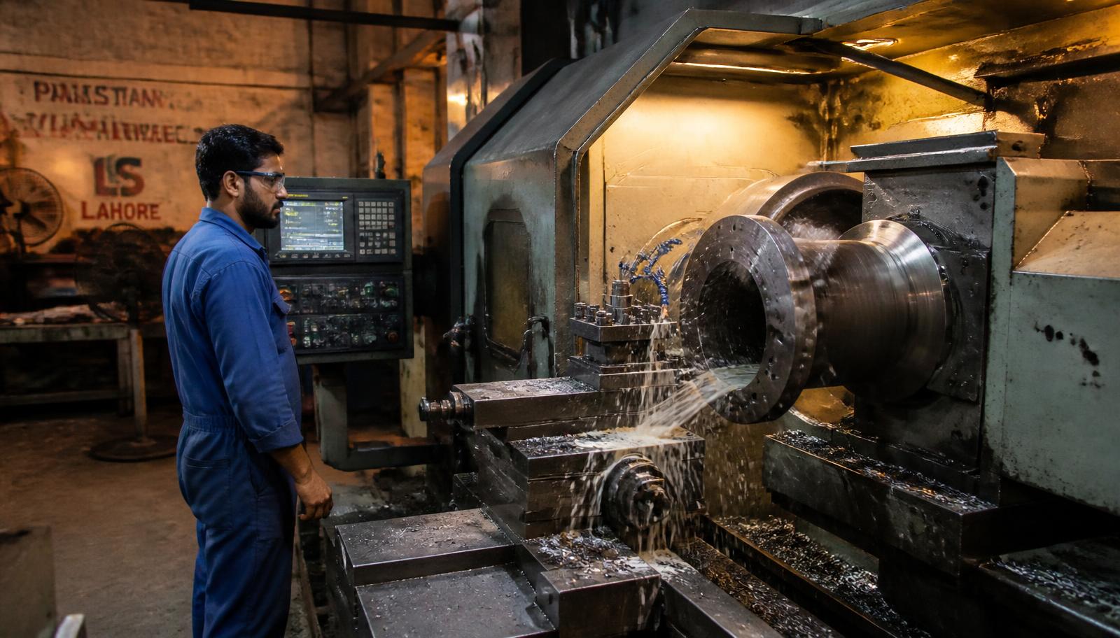
Precision machining of valve body sealing geometry
Workshop · LHR Precision machining of valve body sealing geometry
Quality Assurance

Tested Before It Reaches the Line

Inspection is built into the route card, not added at the end. Each stage has a hold point, and no unit is released without its test record.

Hold Point 1

Incoming Material

Grade verification and heat-number recording against the mill certificate.

Hold Point 2

Dimensional Check

Face-to-face, bore, flange drilling and seat geometry against the approved drawing.

Hold Point 3

Hydrostatic Shell Test

Pressure boundary tested above design pressure with zero visible leakage permitted.

Hold Point 4

Seat Tightness Test

Closure member tested in both directions where the design is bidirectional.

Hold Point 5

Visual & Coating

Casting surface, weld quality, coating thickness and flange face protection.

Hold Point 6

Documentation

Test certificates and dimensional reports issued with every consignment.

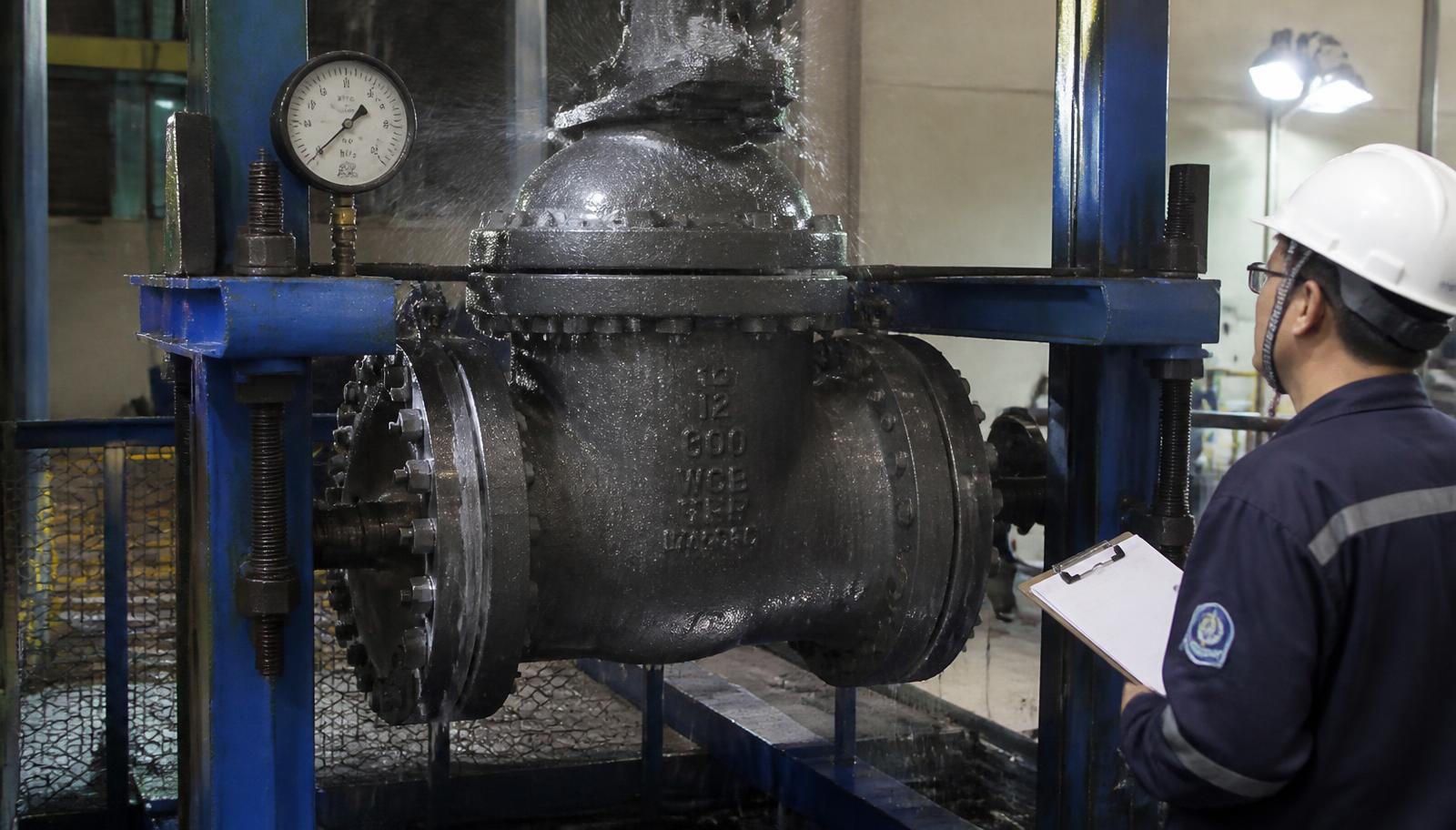
QA · TEST BAY Hydrostatic test bench
Hydrostatic Test Bench · Pressure Hold
Why Engineers Work With REW

Six Practical Reasons

01

Engineering Capability

Equipment is selected against your line list, fluid data and design conditions — not against a catalogue page. Non-standard dimensions and legacy equipment interfaces are handled from drawing or sample.

02

Manufacturing Under One Roof

Casting, machining, assembly, testing and coating are managed in our own Lahore facility. Sequence and quality decisions stay with the people accountable for the finished unit.

03

Technical Support

Direct access to engineers for selection, material queries, torque and NPSH questions, and installation guidance — before the order and after commissioning.

04

Documented Quality

ISO 9001:2015 certified system. Material certificates, dimensional records and pressure test results issued with each consignment for audit and traceability.

05

Service Life

Material grade, trim hardness and surface finish are specified for the actual duty, so replacement intervals are driven by process conditions rather than by manufacturing shortcuts.

06

Maintainability

Standard internals, replaceable trim and locally available spare parts keep overhaul time and lead time short — a decisive advantage during unplanned shutdowns.

Technical FAQ

Engineering Questions

Questions most often raised by design, operations and procurement teams working on hydrocarbon systems.

Choose a gate valve where the valve stays in one position for long periods, where a straight full-bore passage and very low pressure drop matter, and where slow, controlled closure is preferred. Choose a ball valve where fast quarter-turn operation, tight shut-off and frequent cycling are required. Neither should be used for throttling.
In a partially open gate valve, flow accelerates across a narrow gap between disc and seat. The resulting high-velocity jet erodes the seating faces, and vibration of the disc wears the guide surfaces. The valve then fails to seal in the closed position — the function it was actually installed for.
It limits hardness and controls chemistry and heat treatment of components exposed to wet H₂S, to prevent sulphide stress cracking. The requirement covers body, bonnet, stem, bolting, trim and any weld overlay — a compliant body with non-compliant bolting is not a compliant valve.
A secondary metal-to-metal seat takes over sealing when the soft seat is destroyed by fire, combined with graphite stem packing and body gaskets that survive high temperature, and an anti-static path across stem and ball. The design is verified by burn testing to API 607 or API 6FA.
Control the closure rate relative to the pipeline's pressure wave travel time. On long liquid lines, a rapid quarter-turn closure can generate a surge that exceeds the pipe's design pressure. Use gear operators or actuators with a defined stroke time, and confirm the closure time against a surge analysis for the line.
Chatter occurs when the flow velocity is too low to hold the disc firmly against its stop, so the disc oscillates and wears the hinge pin. It is almost always caused by oversizing. Size the check valve on actual minimum operating flow, not on line size, and consider a spring-assisted design for variable-flow duty.
Packing consolidation and relaxation after thermal cycling, a scored or corroded stem surface, and misaligned gland loading. Live-loaded packing with disc springs, a fine-ground stem finish, and correct gland torque keep sealing load stable over the cycling life of the valve.
The two requirements can conflict: erosion resistance suggests hard trim, while sour service caps hardness. The usual resolution is a hardness-controlled base material with a qualified hardfacing overlay that meets the sour-service hardness limit, plus a full-bore geometry that avoids local velocity peaks.
The shell test pressurises the assembled pressure boundary with the closure member partly open, typically at 1.5 times the design pressure at 38 °C, and confirms body and joint integrity. The seat test pressurises against the closed obturator at a lower pressure, typically 1.1 times rated pressure, and verifies sealing of the closure member.
Specify full-bore construction with a bore diameter matching the pipeline internal diameter, no internal cavities or steps at the seat, and a body length that allows the pig to pass without tilting. A reduced-bore valve anywhere in the pigged section will stop the pig.
Line size and piping class, design pressure and temperature, fluid composition including H₂S and CO₂ content, operating duty (isolation, throttling, ESD), end connection type, required standard, actuation requirement, and any documentation or testing beyond our standard scope.
Yes. Parts are produced from the original drawing, a dimensioned sketch, or by measuring a sample component. Material grade is matched to the original or upgraded where the failure history suggests the original grade was marginal for the duty.
Store in the fully closed or fully open position as supplied, with flange protectors in place, under cover and off the ground. Do not remove preservation coating early. Before installation, confirm the bore is clean, the seat faces are undamaged, and the gland torque is correct after storage.
Periodic exercising through partial or full stroke to prevent seizure, gland torque checks, stem lubrication where applicable, recording of operating torque as a trend indicator, and visual inspection of coating and external corrosion. Rising operating torque is usually the earliest warning of internal damage.
NPSH available in your system must exceed the pump's NPSH required by a clear margin at the duty point and at the maximum expected flow. Volatile hydrocarbons and elevated temperatures reduce NPSH available significantly. Provide suction line layout, fluid temperature and vapour pressure so the margin can be verified rather than assumed.
Project Enquiry

Send Us the Line Data

Share your line list, piping class or a marked-up P&ID and our engineering team will confirm suitable equipment, materials and testing scope. For spare parts, a photograph of the nameplate or the worn component is usually enough to begin.

Direct Lines

Route your enquiry to the right desk and you will get an engineering answer, not a sales script.

Enquiries

Valve and pump selection, material queries, technical clarifications

Procurement

Budgetary and firm quotations, delivery schedules, documentation scope

Maintenance

Spare parts, rebuild kits, turnaround support

Facility · Rehman Engineering Works
Lahore, Pakistan · Manufacturing since 1948
Your details are only used to respond to this enquiry.