Flow Control For
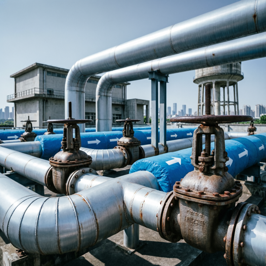
From raw water intake to the consumer connection, a supply scheme is only as reliable as the components that isolate, protect and regulate it. Rehman Engineering Works designs and manufactures valves for transmission mains, pumping stations, reservoirs and distribution networks — cast, machined, assembled and pressure tested at a single works in Lahore.
 REF · WS-2026
Transmission Main · Valve Installation
REF · WS-2026
Transmission Main · Valve Installation
Water Supply Is A Continuity Problem
A municipal scheme is judged on one thing: whether treated water arrives at the required pressure, every day, without interruption. Hydraulic design sets the target; the mechanical components decide whether the network holds it over twenty or thirty years of service.
Transmission Networks
Bulk mains carry treated water from the works to the demand centre, often over tens of kilometres at high static head. Isolation at intervals, air management at every high point and washouts at every low point decide whether a burst means a two-hour outage or a two-day one.
Pumping Stations
Pump sets impose the harshest duty in the network: repeated starts, reverse flow on trip, and surge. Suction isolation, discharge non-return and surge protection must be sized as a set, not selected item by item.
Storage Reservoirs
Ground and elevated reservoirs buffer diurnal demand and hold fire reserve. Inlet control, level control, scour and overflow arrangements determine turnover, and turnover determines water quality in the tank.
Distribution Zones
Below roughly DN 400 the network becomes a grid. District Metered Areas need clean boundary isolation, pressure reduction at the inlet, and valves that will still turn after ten years buried in a chamber.
Service Reliability
Continuity depends less on pipe strength than on the ability to isolate a small section quickly. Valve spacing, chamber access and accurate as-built records are the difference between a planned shutdown and a city-wide one.
Infrastructure Ageing
Much of Pakistan's urban distribution was laid decades ago and now runs intermittently. Replacement programmes need components that suit variable pressure, silted water and limited maintenance access — not laboratory conditions.

Source To Consumer, Stage By Stage
Each stage imposes a different duty on the flow control equipment installed in it. Select a stage to see its purpose, engineering requirement, control requirement and typical products.
Water Source
What Actually Fails In A Supply Network
These are the recurring failure modes in municipal water systems, and the design responses that address them. None of them are solved by a single component — but each of them can be made worse by the wrong one.
Pressure Management
Pressure high enough for the far end of a zone bursts service pipes at the near end, especially where ground level varies.
Leakage & Non-Revenue Water
Distribution losses in ageing intermittent networks are dominated by joints, service connections and passing valves.
Water Hammer & Surge
Pump trip or fast valve closure generates pressure waves several times the working head, cracking fittings and collapsing thin-wall pipe under vacuum.
Corrosion
Buried chambers flood, coatings get damaged during handling, and dissimilar metals in one flange joint set up galvanic cells.
Ageing Infrastructure
Existing mains often have unknown condition, non-standard flanges and valves that no longer turn.
Maintenance Access
A valve that cannot be reached is a valve that will not be operated during an emergency.
Flow Isolation
Too few sectionalising valves means shutting a whole district to repair one joint.
Silt & Abrasive Solids
Canal-fed and tubewell supplies carry sand that scores seats and jams gates.
Operational Efficiency
Throttled isolation valves and undersized fittings waste pump energy for the life of the scheme.
Safety & Potable Integrity
Backflow from a contaminated branch or a submerged chamber can compromise the supply.
Equipment Specified For Water Duty
Only products suited to potable and raw water service are listed. Each entry states where it is installed, why it is chosen and the operating envelope it is normally supplied within.
Gate Valve — Sluice Valve
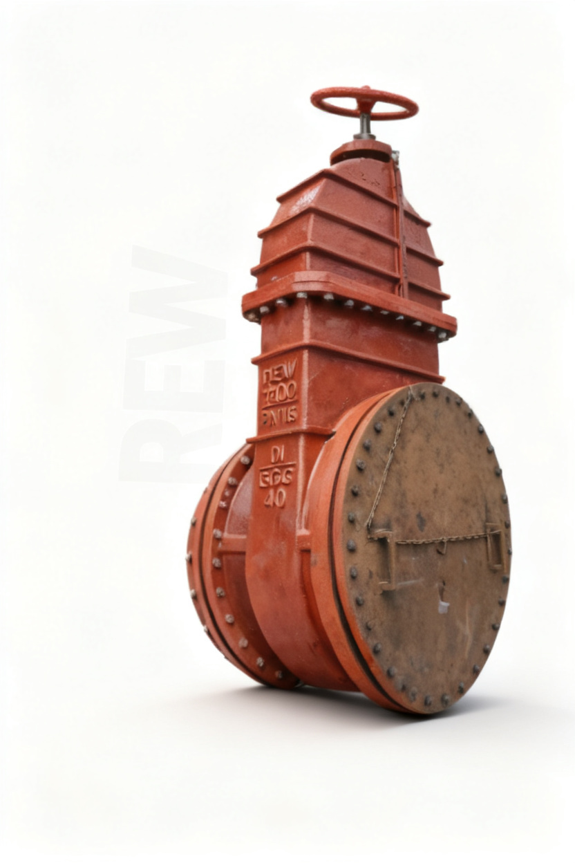
Full-bore on/off isolation. The wedge withdraws clear of the bore, leaving an unobstructed waterway and negligible head loss.
- Unobstructed full bore — minimal pressure drop in service
- Rising spindle for visible position above ground; non-rising for buried chambers
- Resilient or metal seating to suit water quality
- Bi-directional shut-off; no preferred flow direction
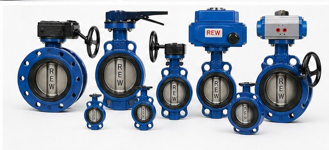
Butterfly Valve
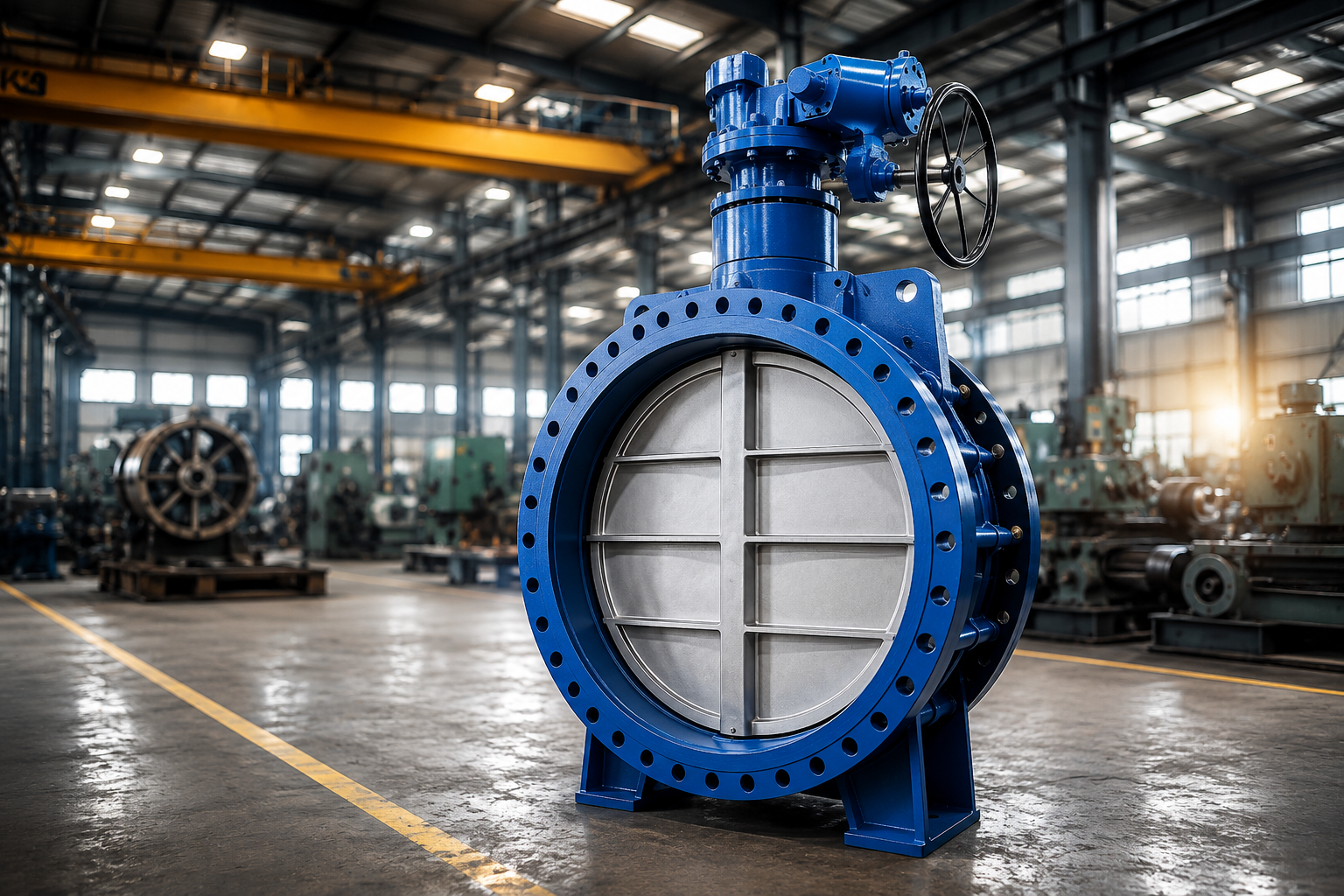
Compact quarter-turn isolation and coarse regulation where face-to-face length and weight are limited.
- Short face-to-face — suits congested pump houses and chambers
- Quarter-turn operation; gearbox, electric or pneumatic actuation
- Low weight per DN compared with gate valves at large sizes
- Resilient liner gives tight shut-off on clean water
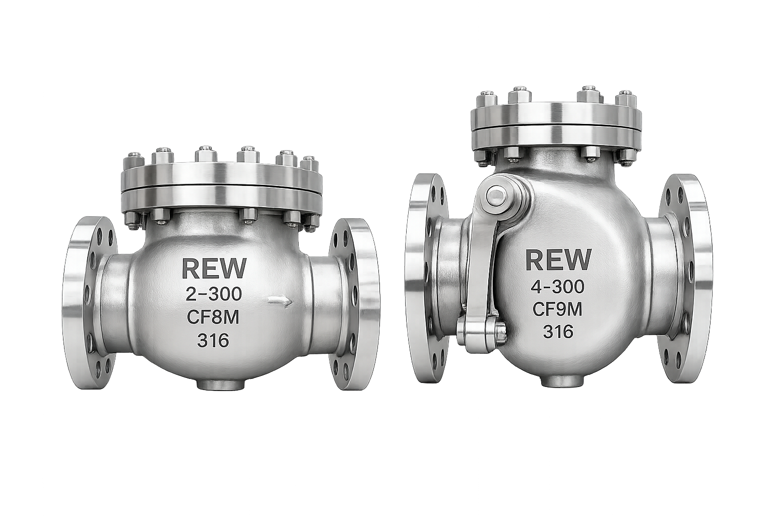
Non-Return / Check Valve
Prevents reverse flow on pump trip and protects the column above the pump set.
- Automatic — no operator action required
- Swing, dual-plate and nozzle patterns to suit surge behaviour
- Damped closure options to limit slam on high-head sets
- Serviceable seat and hinge pin
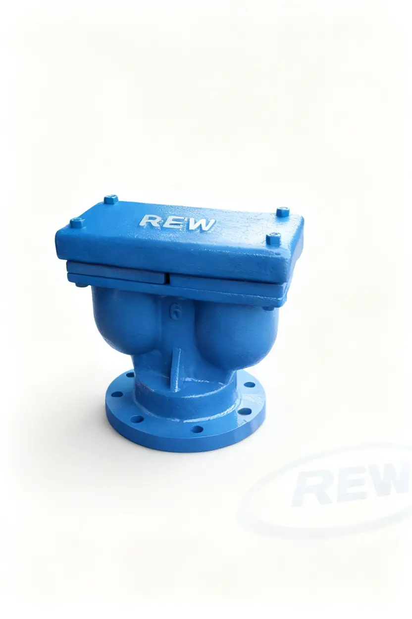
Air Release & Vacuum Break Valve
Releases accumulated air at high points during operation and admits air to break vacuum on drain-down or surge.
- Prevents air locks that reduce effective pipe capacity
- Vacuum break protects thin-wall pipe against collapse
- Single, double and triple orifice configurations
- Isolating valve beneath allows service without shutdown
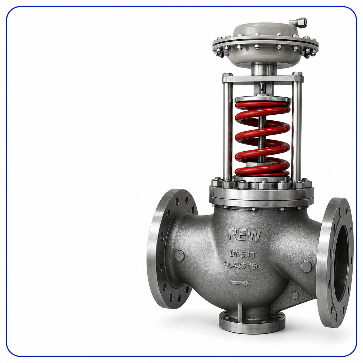
Pressure Reducing Valve
Holds a stable downstream pressure irrespective of upstream variation and demand.
- Reduces burst frequency and background leakage in the zone
- Pilot-operated diaphragm design with adjustable set point
- Can be combined with sustaining or flow-limiting pilots
- Isolation and strainer upstream keeps the pilot circuit clean
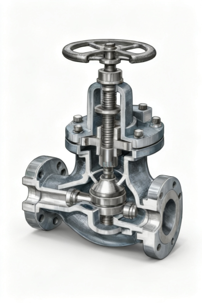
Globe Valve
Regulation and throttling where flow must be set and held, with tight shut-off against the seat.
- Designed for throttling — stable characteristic across the stroke
- Renewable seat and disc
- Tight shut-off with metal or resilient seating
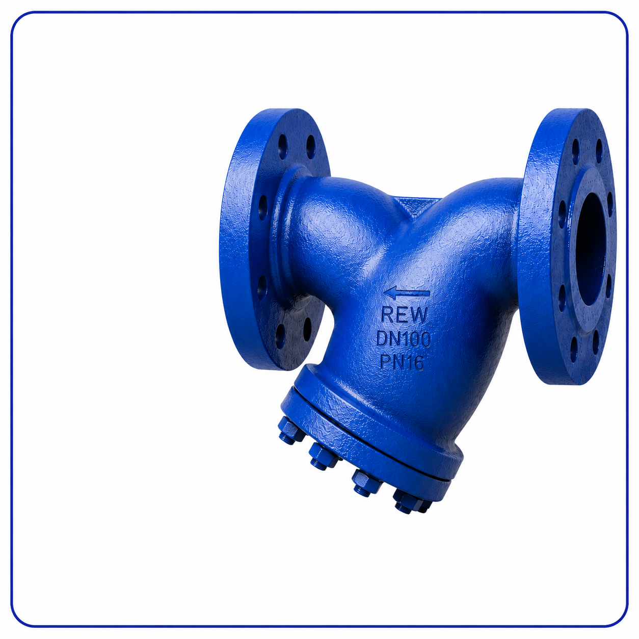
Y-Type Strainer
Removes sand, scale and debris ahead of pumps, meters and control valves.
- Protects seats and pilot circuits from abrasive particles
- Blow-down connection allows cleaning without removal
- Perforated or mesh screens selected on particle size
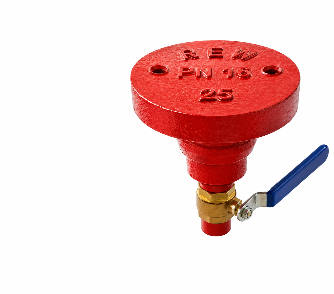
Fire Hydrant & Washout Assembly
Fire-fighting draw-off and network flushing at defined points on the distribution grid.
- Pillar and underground patterns
- Serves as a flushing point for mains cleaning
- Isolating gate valve on the branch for maintenance
Where Each Product Sits In The Network
A conventional municipal supply system, read left to right. The equipment listed under each stage is what a design normally carries at that point — quantities and ratings follow the hydraulic model.
Source & Intake

Service Life Is Decided In The Works
A buried valve is inspected rarely and replaced expensively. Everything that determines whether it still operates in year twenty — melt chemistry, seat concentricity, gland assembly, coating thickness — is fixed before it leaves the factory.
Material Selection
Body material is chosen against the water chemistry and pressure class — grey iron and ductile iron for municipal duty, cast and stainless steel where chloride or temperature demands it. Seat and stem materials are specified separately; the stem is the component that decides whether a buried valve still operates in year fifteen.
Casting & Inspection
Bodies are poured in the in-house foundry with spectro-checked melt chemistry and heat identification carried through to the finished valve. Castings are visually and dimensionally inspected before any machining time is committed.
Precision Machining
Flange faces, seat rings, stuffing box and stem bores are machined on CNC equipment. Seat concentricity and flange flatness are what produce a leak-free joint on site; both are gauged, not assumed.
Assembly
Wedge, stem, bonnet and gland are assembled to a controlled torque sequence with checked gasket and O-ring compression. Every valve is stroked through its full travel and the operating torque recorded.
Pressure Testing
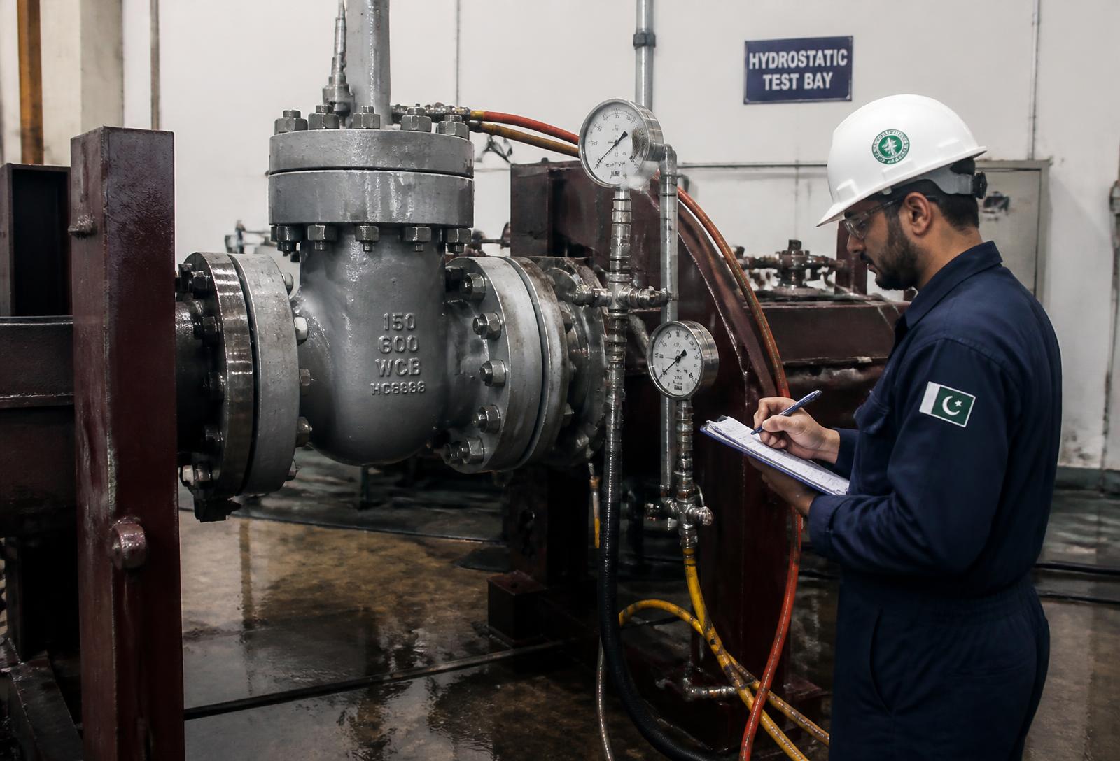
Shell and seat hydrostatic tests are carried out to API 598 / ISO 5208 criteria at the pressures corresponding to the valve rating. Test data is recorded per valve and issued with the consignment on request.
Surface Protection
Surfaces are shot-blasted and coated with epoxy suitable for potable water contact, with dry film thickness checked. Coating integrity is the primary defence for a valve that will sit in a wet chamber for decades.
Capability, Not Claims
What follows is verifiable: manufacturing scope, certification, standards worked to, and the support available during design and after commissioning.
Manufacturing Under One Roof
Foundry, machine shop, assembly and test bay operate on a single site in Lahore. Non-conformance is caught between stages rather than discovered on site.
Established Since 1948
REW has supplied flow control equipment to Pakistani industry and utilities for over seven decades, with product ranges developed against field experience rather than catalogue copying.
Certified Quality System
Quality, environmental and occupational health & safety management systems are certified to ISO 9001:2015, ISO 14001:2015 and ISO 45001:2018.
Standards-Based Design
Valves are built to BS, DIN, ANSI and API dimensional and testing standards, so replacements fit existing flanges and chambers without redesign.
Engineering Support
Selection review against your hydraulic data, face-to-face and flange drilling confirmation, and drawing issue for approval before manufacture.
Spares & Service Life
Seats, glands, stems and gaskets remain available for the installed range, so a valve is repaired in the chamber instead of replaced from the trench.
Fifteen Questions From Water Supply Projects
Selection, installation, testing and maintenance questions raised most often by utility engineers and consultants.
Send Us The Hydraulics, Not Just The Size List
Share the line size, design and transient pressure, fluid condition, operation method and delivery programme. REW reviews the selection against your data and issues general arrangement drawings for approval before manufacture.
Direct Lines
One enquiry, answered by engineers who have stood in the same valve chambers.
Rehman Plaza, Sanda Khurd, Bund Road, Lahore, Pakistan
+92 322 276 2222 · +92 322 266 6007
info@rehmanengg.com · rewpak@yahoo.com
www.rehmanengg.com